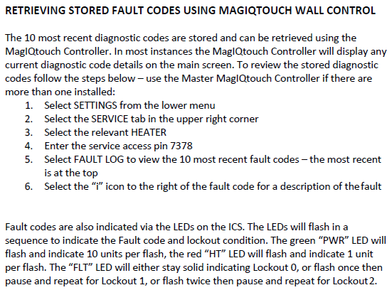
Fault code history can be accessed:
SETTINGS/SERVICE/GAS HEATER 01/7378 CONT/FAULT LOG
YouTube Video - MagIQtouch Heater Fault Log


IDENTIFYING PRESSURE SWITCHES TQ HEATERS
Important: Always refer to the wiring diagram located under the heater lid to ensure all electrical connections are correct.
Two-stage heaters are equipped with two pressure switches: one for high pressure and one for low pressure.
Single-stage heaters have one high-pressure switch.
Condensing two-stage (plastic flue) heaters include a third pressure switch specifically designed to detect condensate.
High Pressure Switch: Connected via spade terminals using blue and red wires.
Blue wire terminates at pin 11 of the 12-pin connector on the ICS board.
Low Pressure Switch: Connected via spade terminals using purple and red wires.
Purple wire terminates at pin 9 of the 12-pin connector on the ICS board.
Red Common Wire: Shared between both pressure switches and supplies 24 VAC.
This red wire originates from pin 8 of the 12-pin connector on the ICS board.


Combustion Fan Suction Pressure – Correct Testing Method for Accurate Readings During Normal Heater Operation
To ensure accurate measurement of combustion fan suction pressure during standard heater operation, follow the correct testing procedure as shown in below images.
Suction pressure should consistently read higher than the activation point, of the high-pressure switch.
As a general guideline, suction pressure should be approximately 20 Pascals above the rated pressure of the high-pressure switch.

