
TQA5X30 FC23 Fault – Room Fan Not Running Diagnostics (Nicotra Interface PCBA)
⚠️ Safety Notice – Gas Heating Products
This appliance must only be installed, commissioned, serviced and repaired by suitably qualified and licensed personnel.
Before commencing work, complete a task-specific risk assessment and ensure gas and electrical safety requirements, ventilation provisions, safe access, adequate service clearances and appropriate PPE have been considered. All work must comply with applicable regulations, standards and manufacturer requirements.
Particular care must be taken when working around gas systems, electrical components, combustion products, hot surfaces, moving parts, roof spaces, ceiling spaces and confined spaces.
Do not proceed if safe access, required clearances, ventilation requirements, confined space risks or appropriate safety controls cannot be achieved and maintained.
Safety takes priority over diagnosis, repairs, installation schedules and customer expectations. If the task cannot be completed safely, it must not proceed until the risks have been adequately controlled.
Fault code history can be accessed:
SETTINGS/SERVICE/GAS HEATER 01/7378 CONT/FAULT LOG
YouTube Video - MagIQtouch Heater Fault Log
Applicable Model
- Braemar TQA5X30 (Nicotra fan with interface PCBA)
Fault Description
- Fault Code 23 – Room fan not running
- Triggered when the system does not detect the room fan reaching operating speed
System Overview (Critical)
The TQA5X30 differs from other TQ/TQM models:
- Uses a Nicotra fan motor
- Does not use a direct motor speed sensor
- Uses a fan interface PCBA (P/N 644011) to:
- Convert control signals to drive the motor
- Send a fan running status signal back to the ICS
FC23 is triggered when this fan running signal is not confirmed
Confirm Fault via ICS LEDs
| LED | Behaviour |
|---|---|
| PWR (Green) | Flashes 2 times |
| HT (Red) | Flashes 3 times |
| FLT | Indicates lockout status |
Confirms FC23 – Room fan not running
Interface Board LED Operation (D2 / D3)
Normal Operation
| Condition | Green (D2) | Red (D3) |
|---|---|---|
| Standby (fan off) | ON | OFF |
| Fan running | OFF | ON |
Diagnostic Procedure (Step-by-Step)
1. Check Interface LEDs at Power Up
- Green LED OFF at power up
- Check wiring from ICS → interface board
- If wiring is OK → replace interface PCBA
2. Fan Not Running (No Attempt to Start)
Symptoms:
- No fan movement
- No start attempt
Check:
- Power supply and fuse to fan
- Wiring:
- Fan → interface board
- ICS → interface board
- Inspect interface PCB for visible damage (components, tracks)
- Confirm power indicator at motor control box
If all checks OK → suspect:
- Fan motor fault, or
- Interface PCBA fault
3. Fan Attempts to Start + RED LED ON (D3 ON)
Meaning:
- Interface is detecting fan movement
- ICS is not receiving correct feedback signal
Check:
- Wiring from ICS → interface board
- If wiring is OK:
- Temporarily disable signal via MagIQtouch:
- SETTINGS → SERVICE → GAS HEATER → 7378 →
Disable Motor Speed Sensor
- SETTINGS → SERVICE → GAS HEATER → 7378 →
- Temporarily disable signal via MagIQtouch:
Outcomes:
- Fault clears → replace ICS
- Fault remains → interface board or wiring issue
4. Fan Attempts to Start + RED LED OFF (D3 OFF)
Meaning:
- Fan may be running but interface board is not detecting it
Check:
- Wiring:
- Fan → interface board
- Inspect interface PCB for damage
Results:
- PCB damaged → replace interface board
- PCB OK → fan motor fault likely
5. Fan Starts Then Fault Occurs During Run
Symptoms:
- Fan starts, then FC23 triggers
- Green LED turns ON, Red LED turns OFF during run
Meaning:
- Loss of fan status signal
Check:
- Motor wiring to interface board
If wiring OK → fan motor fault likely
Wiring Focus (Important)
If multiple components have been replaced and the fault persists:
Focus on:
- Wiring looms
- Connector integrity
- Terminations
Check for:
- Loose connections
- Poor crimps
- Partially seated plugs
- Harness damage
Key Technical Notes
- The interface PCBA must send a valid status signal to the ICS to confirm fan operation
- The system can report FC23 even if the fan is physically running if this signal is missing
- Diagnosis should always separate:
- ✅ Fan operation
- ✅ Interface detection
- ✅ Feedback to ICS
Quick Field Summary
| Condition | Likely Cause |
|---|---|
| No fan activity | Power / motor / wiring |
| Fan running + FC23 | Interface or feedback issue |
| Red LED ON | Interface detecting fan |
| Red LED OFF | Interface not detecting fan |
| Fault during run | Intermittent motor or wiring |
| No interface LEDs | Power or interface failure |
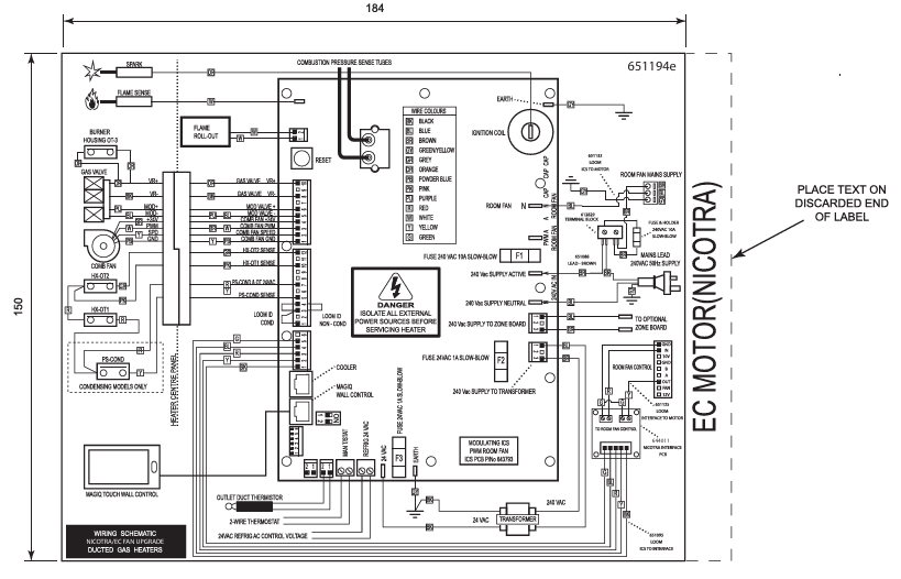
Supplementary Fan Diagnostic (TQA5X30 – Detailed Checks)
This section provides additional checks for the Nicotra fan, interface PCBA, and ICS interaction where FC23 persists.
Fan & Interface Operation Overview
- The TQA5X30 uses a Nicotra DDMP fan with interface PCBA
- The interface board:
- Converts ICS signal to 0–10V DC for fan control
- Sends a 50Hz status signal back to ICS to confirm fan operation
Room Fan Start Sequence (Reference)
- Fan starts approx. 10 seconds after ignition
- Fan speed gradually increases based on thermistor outlet air temperature
If this sequence is not observed, proceed with checks below.
Fan Wiring & Connection Checks
With power isolated:
- Confirm secure wiring at:
- ICS → interface board
- Interface board → fan motor
- Check all connectors:
- Fully seated
- No bent pins
- No loose or partially engaged plugs
- Inspect for:
- Harness damage
- Pinched or stretched wiring
Wiring faults are a common cause of intermittent FC23
Room Fan Motor Checks
- Manually rotate fan:
- Should spin freely without resistance
- Check for:
- Obstructions
- Loose fan wheel or mounting
- Confirm correct installation alignment
A seized or partially restricted fan may fail to generate a valid run signal
Fan Speed and Control Behaviour
- Fan operation is controlled via ICS based on:
- Thermistor temperature
- Set maximum fan speed
- Confirm:
- Fan speed settings not limited too low
- System is calling for heat (fan will not start otherwise)
Incorrect setup can delay or prevent fan operation
Interface PCBA Function Check
The interface board performs two key functions:
Fan Control Output
- Converts ICS signal to drive Nicotra motor
Fan Status Feedback
- Sends signal to ICS confirming fan is running
If Fan Runs but FC23 Remains
- Interface is not sending correct feedback signal
- Check:
- Wiring continuity to ICS
- Interface PCB condition
If wiring is OK → replace interface PCBA
If No Fault Found After All Checks
- Confirm:
- Wiring correct
- Fan operates correctly
- Interface board functioning
If all above checks pass → contact Technical Support for further diagnosis
Important Notes
- The system relies on feedback confirmation, not just fan movement
- A running fan without correct feedback will still trigger FC23
- Always verify:
- ✅ Mechanical operation
- ✅ Electrical supply
- ✅ Feedback signal
Quick Add-On Summary
- Fan spins but FC23 → Interface or signal issue
- Fan does not spin → Power / motor / wiring
- Intermittent fault → Wiring or connection issue