
⚠️ Safety Notice – Reverse Cycle Air Conditioners
This equipment must only be installed, commissioned, serviced and repaired by suitably qualified and licensed personnel.
Before commencing work, complete a task-specific risk assessment and ensure electrical isolation procedures, safe access, adequate service clearances and appropriate PPE have been considered. All work must comply with applicable regulations, standards and manufacturer requirements.
Particular care must be taken when working around electrical systems, refrigerant circuits, moving parts, roof spaces, ceiling spaces, confined spaces and working-at-heights hazards where applicable.
Do not proceed if safe access, required clearances, confined space risks or appropriate safety controls cannot be achieved and maintained.
Safety takes priority over diagnosis, repairs, installation schedules and customer expectations. If the task cannot be completed safely, it must not proceed until the risks have been adequately controlled.
LCHV / BCHV / WCHV / KCHV Series Reverse Cycle Inverter Systems
Applicable Models
High Wall Split Systems
- KSHV / KCHV Series
- BSHV / BCHV Series
- LSHV / LCHV Series
- WSHV / WCHV Series
Inverter Ducted Systems
- SDHV / SCHV Series
Cassette Systems
- SBHV / SCHV Series
Multi Systems
- MSHV / SCHV Series
- MDHV Series
- MBHV Series
Fast Technician Reference
| Code Range | Area to Check First |
|---|---|
| F1–F5, L1 | Sensors and wiring |
| E6, UF, P6 | Communications wiring |
| E1, E3, E4, F0 | Refrigeration circuit |
| H3, H5, E5 | Compressor and inverter |
| PH, PL, HC | Power supply |
| L3, LA, P8 | Outdoor fan and airflow |
| EE, P7, C5 | PCB faults |
Fault Code Summary
| Fault Code | Fault Description | Sensor Type |
|---|---|---|
| F1 | Indoor Ambient Temperature Sensor Fault | 15K NTC |
| F2 | Indoor Coil / Evaporator Temperature Sensor Fault | 20K NTC |
| F3 | Outdoor Ambient Temperature Sensor Fault | 15K NTC |
| F4 | Outdoor Coil / Condenser Temperature Sensor Fault | 20K NTC |
| F5 | Outdoor Discharge Temperature Sensor Fault | 50K NTC |
| L1 | Temperature & Humidity Sensor Fault | 100K NTC |
Symptoms
The system may exhibit one or more of the following:
- Unit will not start
- Compressor stops operating
- Indoor fan may continue running
- Heating or cooling performance reduced
- Fault code displayed on controller or indoor unit
- Intermittent operation
- Fault code returns after reset
Safety Notice
⚠️ Isolate power before disconnecting sensors or performing resistance measurements.
Resistance testing must be performed with the sensor disconnected from the control board to avoid inaccurate readings.
Troubleshooting Procedure
Step 1 - Inspect Sensor Connection
Check:
- Sensor plug is fully inserted into the PCB
- Loose terminals
- Corrosion or moisture ingress
- Damaged wiring
- Pinched or crushed cables
Fault Found?
Yes
- Repair connection.
- Restore power and retest unit.
No
- Proceed to Step 2.
Step 2 - Inspect Sensor Wiring
Check the entire harness between the sensor and PCB for:
- Open circuit wiring
- Damaged insulation
- Short circuit to copper tubing
- Short circuit to cabinet metalwork
- Burnt connectors
Fault Found?
Yes
- Repair or replace wiring.
- Restore power and retest.
No
- Proceed to Step 3.
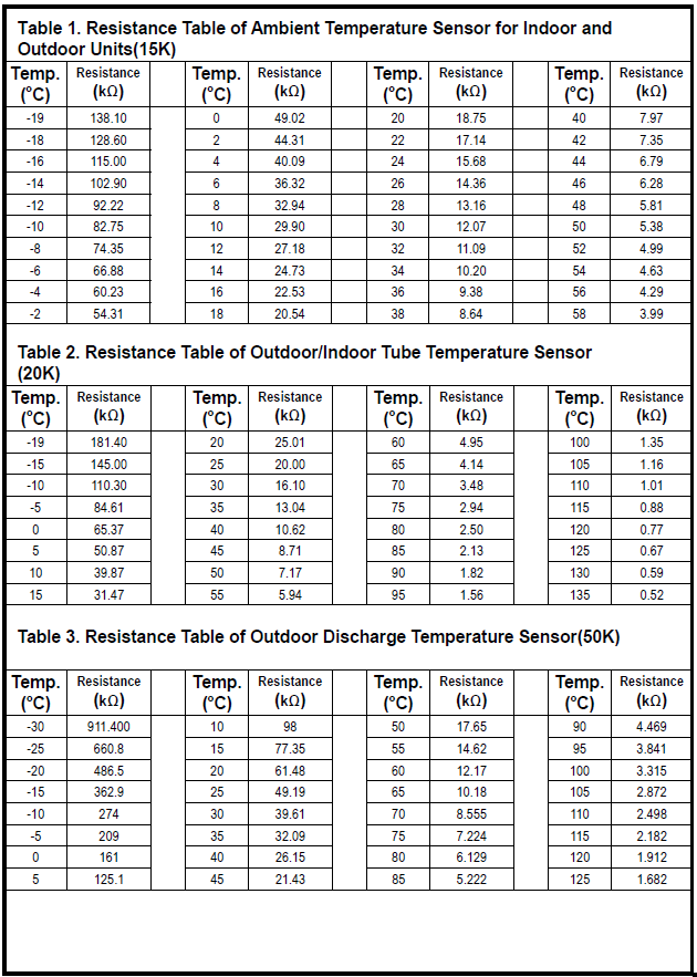
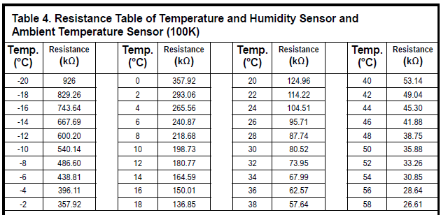
Step 3 - Measure Sensor Resistance
Disconnect the sensor from the control board.
Using a multimeter, measure resistance across the sensor terminals.
Compare the reading to the applicable resistance table below.
Resistance Within Specification?
Yes
- Proceed to Step 4.
No
- Replace the sensor.
- Restore power and confirm fault is cleared.
Step 4 - PCB Inspection
If:
- Wiring is correct
- Sensor resistance is correct
- Connections are secure
The fault is likely caused by:
- PCB input circuit failure
- Dry solder joint
- Control board fault
Action
Replace the relevant control board and retest.
Sensor Resistance Tables
F1 & F3 – Ambient Temperature Sensor (15K NTC)
| Temp °C | Resistance kΩ |
|---|---|
| 0 | 49.02 |
| 10 | 29.90 |
| 20 | 18.75 |
| 30 | 12.07 |
| 40 | 7.97 |
| 50 | 5.38 |
F2 & F4 – Coil Temperature Sensor (20K NTC)
| Temp °C | Resistance kΩ |
|---|---|
| 0 | 65.37 |
| 10 | 39.87 |
| 20 | 25.01 |
| 30 | 16.10 |
| 40 | 10.62 |
| 50 | 7.17 |
F5 – Discharge Temperature Sensor (50K NTC)
| Temp °C | Resistance kΩ |
|---|---|
| 0 | 161.0 |
| 10 | 98.0 |
| 20 | 61.48 |
| 30 | 39.61 |
| 40 | 26.15 |
| 50 | 17.65 |
L1 – Temperature & Humidity Sensor (100K NTC)
| Temp °C | Resistance kΩ |
|---|---|
| 0 | 357.92 |
| 10 | 198.73 |
| 20 | 124.96 |
| 30 | 80.52 |
| 40 | 53.14 |
| 50 | 35.88 |
Quick Diagnosis Guide
| Fault Code | Sensor Location | Most Common Cause |
|---|---|---|
| F1 | Indoor ambient sensor | Loose connector or failed sensor |
| F2 | Indoor evaporator sensor | Sensor disconnected or coil sensor failure |
| F3 | Outdoor ambient sensor | Damaged outdoor sensor wiring |
| F4 | Outdoor condenser sensor | Sensor shorted to copper pipe |
| F5 | Outdoor discharge sensor | Failed discharge sensor or damaged wiring |
| L1 | Indoor temperature/humidity sensor | Failed humidity sensor or PCB fault |
Repair Outcome
After repairs:
- Restore power.
- Clear any active alarms by power cycling the unit.
- Operate the system in heating and cooling modes.
- Confirm the fault code does not return.
LCHV / BCHV / WCHV / KCHV Series Error Code Quick Lookup Table
Sensor Faults
| Code | Fault Description | Sensor Location | Likely Causes |
|---|---|---|---|
| F1 | Indoor Ambient Temperature Sensor Fault | Return air sensor | Loose connection, faulty sensor, damaged wiring, indoor PCB fault |
| F2 | Indoor Coil / Evaporator Temperature Sensor Fault | Indoor coil sensor | Loose connection, faulty sensor, damaged wiring, indoor PCB fault |
| F3 | Outdoor Ambient Temperature Sensor Fault | Outdoor air sensor | Faulty sensor, wiring short/open circuit, outdoor PCB fault |
| F4 | Outdoor Coil / Condenser Temperature Sensor Fault | Outdoor coil sensor | Faulty sensor, wiring short/open circuit, outdoor PCB fault |
| F5 | Outdoor Discharge Temperature Sensor Fault | Compressor discharge pipe | Faulty sensor, damaged wiring, outdoor PCB fault |
| L1 | Temperature & Humidity Sensor Fault | Indoor humidity sensor | Faulty sensor assembly, wiring fault, PCB fault |
| b5 | Gas Pipe Temperature Sensor Fault | Outdoor refrigerant pipe | Sensor failure, short circuit, PCB fault |
| b7 | Gas Valve Temperature Sensor Fault | Refrigerant circuit | Sensor failure, damaged wiring, PCB fault |
| PF | Ambient Temperature Sensor Fault (Drive Board) | Outdoor drive board | Faulty sensor or drive PCB |
Communication Faults
| Code | Fault Description | Likely Causes |
|---|---|---|
| E6 | Indoor ↔ Outdoor Communication Fault | Wiring fault, indoor PCB fault, outdoor PCB fault |
| UF | Indoor Unit ↔ Display Board Communication Fault | Damaged communication wiring, display board failure |
| P6 | Main Board ↔ Drive Board Communication Fault | Communication wiring fault, drive board fault |
| rF | RF Module Fault | RF module disconnected or faulty |
| E6 (Window Unit) | Wired Controller Communication Fault | Wiring fault, controller fault, PCB fault |
Compressor Protection Faults
| Code | Fault Description | Likely Causes |
|---|---|---|
| H3 | Compressor Overload Protection | Refrigerant issues, airflow restriction, compressor fault |
| H5 | IPM Protection | Module overheating, compressor issue, power supply problem |
| E1 | High Pressure Protection | Dirty condenser, blocked airflow, high refrigerant charge |
| E3 | Low Pressure Protection | Low refrigerant charge, low pressure switch fault |
| E4 | High Discharge Temperature Protection | Restricted airflow, blockage, sensor issue |
| E5 | AC Overcurrent Protection | High current draw, compressor issue, supply voltage problem |
| L9 | High Power Protection | Excessive system load |
| P5 | Over-Phase Current Protection | Compressor electrical fault |
| U2 | Lost Phase Protection | Supply phase loss or compressor fault |
| HE | Compressor Demagnetisation Protection | Compressor or power module issue |
Power Supply / Electrical Faults
| Code | Fault Description | Likely Causes |
|---|---|---|
| HC | PFC Protection | Unstable power supply, PFC circuit fault |
| PH | DC Bus Voltage Too High | High supply voltage |
| PL | DC Bus Voltage Too Low | Low supply voltage |
| U3 | DC Bus Voltage Drop | Unstable power supply |
| Ld | Lost Phase Fault | Phase loss, compressor wiring issue |
| U1 | Phase Current Detection Circuit Fault | Outdoor PCB fault |
Outdoor Unit Faults
| Code | Fault Description | Likely Causes |
|---|---|---|
| L3 / LA | Outdoor Fan Motor Fault | Fan motor failure, motor wiring fault, outdoor PCB fault |
| oE | Undefined Outdoor Unit Fault | Extreme outdoor conditions, sensor faults, PCB issue |
| U9 | Outdoor Unit Zero-Crossing Fault | Outdoor PCB fault |
| P8 | Module Overheating Protection | Restricted airflow, dirty coil, IPM overheating |
| FF | Outdoor Photoelectric Sensor Fault | Sliding door obstruction or sensor fault |
Compressor Starting & Synchronisation Faults
| Code | Fault Description | Likely Causes |
|---|---|---|
| LC | Start-Up Failure | Compressor starting fault, PCB fault |
| H7 | Compressor Desynchronisation | Compressor failure, inverter control issue |
| U5 | Current Detection Fault | Low refrigerant, PCB fault |
Refrigeration System Faults
| Code | Fault Description | Likely Causes |
|---|---|---|
| F0 | Refrigerant Shortage Protection | Low refrigerant charge, restriction, leak |
| PU | Capacitor Charging Fault | Capacitor or charging circuit fault |
| U7 | 4-Way Valve Fault | Faulty valve, wiring issue, low voltage |
PCB / Electronics Faults
| Code | Fault Description | Likely Causes |
|---|---|---|
| EE | EEPROM Fault | Outdoor PCB failure |
| P7 | Module Temperature Sensor Circuit Fault | Outdoor PCB failure |
| C5 | Jumper Cap Fault | Missing or damaged jumper, PCB fault |
| C4 | Outdoor Unit Jumper Cap Fault | Jumper missing or incorrectly fitted |
Capacity & System Configuration Faults
| Code | Fault Description | Likely Causes |
|---|---|---|
| LP | Indoor and Outdoor Unit Mismatch | Incorrect model combination, addressing issue |
| E7 | Mode Conflict | Multiple indoor units calling for opposing modes (heat/cool) |
Status Codes (Not Faults)
| Code | Meaning |
|---|---|
| E2 | Coil Anti-Freeze Protection Active |
| E9 | Anti-Cold Air Protection Active |
| H1 | Defrost Cycle Active |
| High Temp Condenser Protection | Normal protective operation |
| Anti-Freezing Protection | Normal protective operation |
| High Temp Evaporator Protection | Normal protective operation |
| Frost Prevention | Normal protective operation |