⚠️ Safety Notice – Commercial Evaporative Cooling Products
This equipment must only be installed, commissioned, serviced and repaired by suitably qualified and licensed personnel.
Before commencing work, complete a task-specific risk assessment and ensure safe roof access, fall protection requirements, electrical isolation procedures, service clearances and appropriate PPE have been considered. All work must comply with applicable regulations, standards and manufacturer requirements.
Particular care must be taken when working at heights, in roof spaces, ceiling spaces and other restricted access areas. Additional consideration must be given to confined working conditions, electrical hazards, moving parts, water systems, wet surfaces, manual handling risks and weather conditions.
Do not proceed if safe access, weather conditions, required clearances, confined space risks or appropriate safety controls cannot be achieved and maintained.
Safety takes priority over diagnosis, repairs, installation schedules and customer expectations. If the task cannot be completed safely, it must not proceed until the risks have been adequately controlled.
Climate Wizard post-2020 manufactured control system using PLC interface
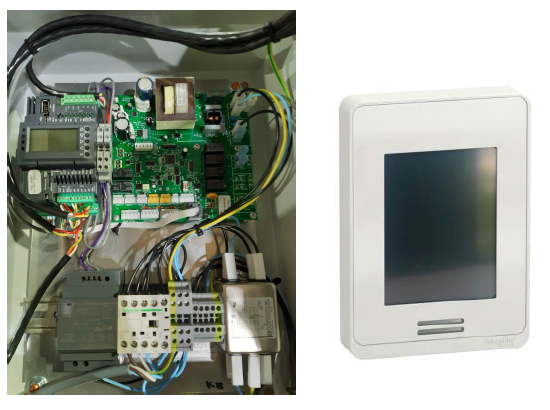

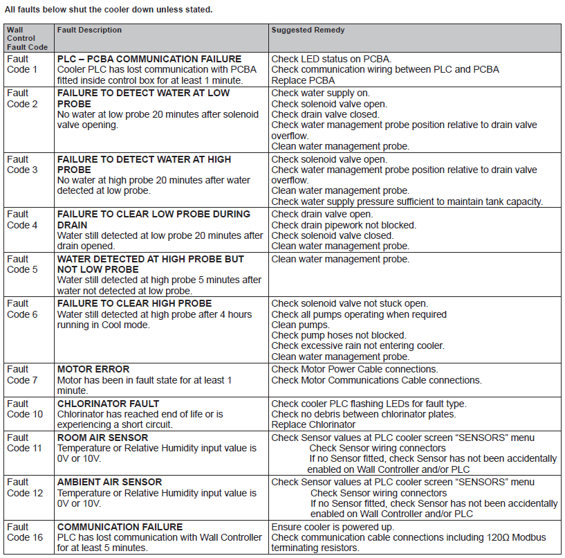
MOTOR ERROR FC7 - DIAGNOSTICS (CW-H PLC VERSION)
Once the fault has been reset and the impellor confirmed free to spin by hand (with power off)
If the motor doesn't spin.
- Check incoming mains, L-N and phase imbalance.
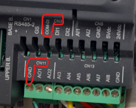
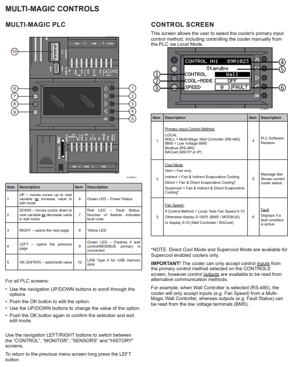
- Check 0-10V speed signal output from PLC (CN11 AO1 and CN11 GND)
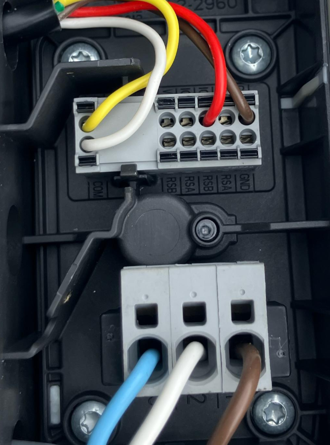
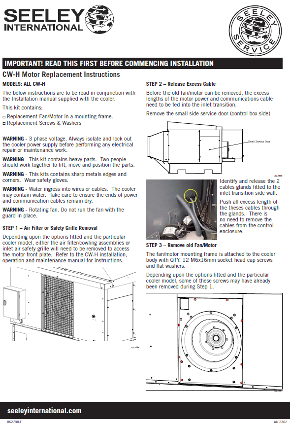
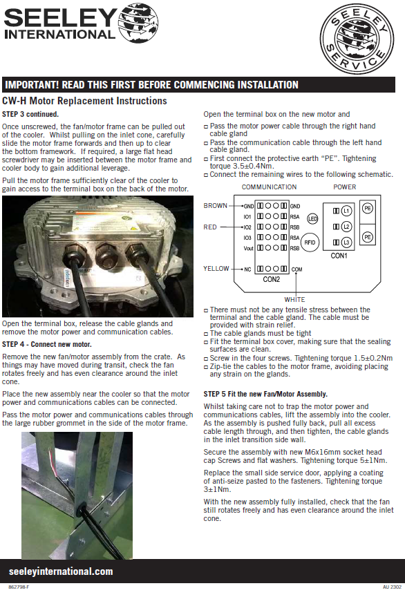
- Pull out motor and check connections.
If the motor spins and the fault returns intermittently
- Most likely transitory mains power issue, typically dipping voltages or phase imbalance
If the motor spins and the fault reoccurs within one minute
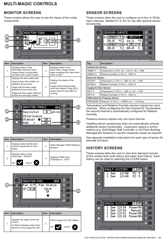
- Check the fan status signal.
- Page 21 of the product manual describes the Fan Status display on the PLC
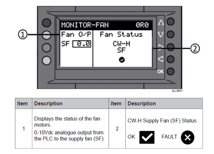
- From PLC software release 89R1023, the Tick/Cross provides a live indication of the fan status.
- If the fan is spinning and there is a Cross, then there is a problem with the communication wiring.
The below link wire method can be used for test purposes only and must not be left indefinitely. It simply bypasses the back of the motor and will forces the fan status to a Tick.
- On PLC, using a short piece of wire link between CN3 COM D1 and CN11 GND.
- CN3 is on the lower (rear) terminal block strip and CN11 on the top row.
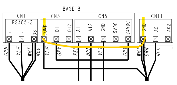
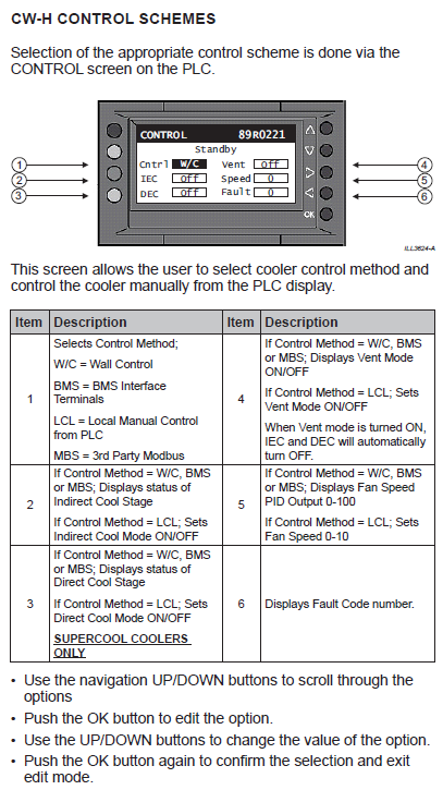
Different software versions provide various screen displays - below are two distinct screen displays.
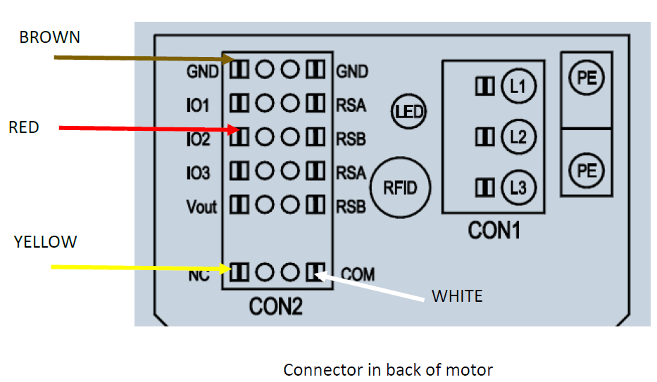
WIRING CONNECTIONS IN BACK OF MOTOR BELOW