
VRF Commissioning Procedure (MCHX & MCRX)
⚠️ Safety Notice – Reverse Cycle Air Conditioners
This equipment must only be installed, commissioned, serviced and repaired by suitably qualified and licensed personnel.
Before commencing work, complete a task-specific risk assessment and ensure electrical isolation procedures, safe access, adequate service clearances and appropriate PPE have been considered. All work must comply with applicable regulations, standards and manufacturer requirements.
Particular care must be taken when working around electrical systems, refrigerant circuits, moving parts, roof spaces, ceiling spaces, confined spaces and working-at-heights hazards where applicable.
Do not proceed if safe access, required clearances, confined space risks or appropriate safety controls cannot be achieved and maintained.
Safety takes priority over diagnosis, repairs, installation schedules and customer expectations. If the task cannot be completed safely, it must not proceed until the risks have been adequately controlled.
Quick Navigation
TABLE OF CONTENTS
- Quick Navigation
- Before Starting Commissioning
- What Does A0 Mean?
- Common Reasons A0 Does Not Appear
- Communication Wiring Requirements
- 120Ω Communication Resistor
- Refrigerant Requirements
- Y-Branch Installation
- Start Commissioning
- Debugging Sequence
- Technician Action Required During Commissioning
- Commissioning Fault Codes & Corrective Actions
- Most Common Commissioning Failures
- Successful Commissioning
- Technician Sign-Off Checklist
Overview
This article explains how to commission Braemar VRF systems after installation has been completed.
Applicable to:
- MCHX Heat Pump VRF
- MCRX Heat Recovery VRF
Useful Links to helpful solutions: -
VRF REVERSE CYCLE SERVICE AND INSTALLATION
Back to top - Table of Contents
Before Starting Commissioning
Before commissioning, ensure:
✅ Pipework completed
✅ Drainage completed
✅ Electrical wiring completed
✅ Controllers installed
✅ Communication wiring completed
✅ Refrigerant charge calculated
✅ Pressure test completed
✅ Vacuum completed to 500 microns
✅ Service valves opened
✅ Additional refrigerant added
✅ Outdoor unit powered for minimum 8 hours
✅ All indoor units powered
✅ Outdoor unit displaying A0
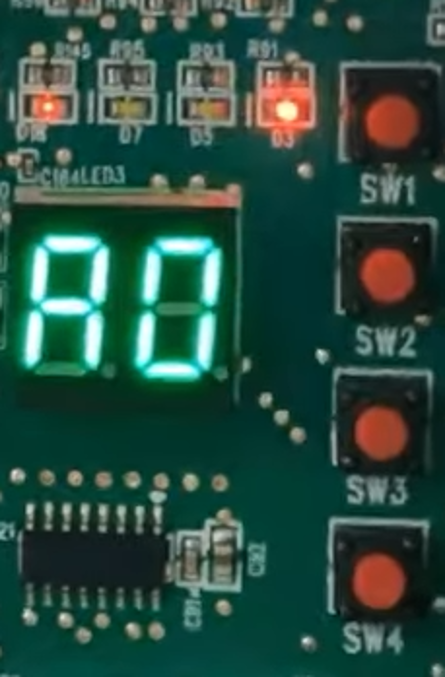
Outdoor unit display showing A0, indicating the VRF system is ready for commissioning.
Back to top - Table of Contents
⚠️ CRITICAL: COMPRESSOR PREHEAT REQUIRED
Do NOT start VRF commissioning until the outdoor unit has been powered continuously for a minimum of 8 hours.
The compressor crankcase heater requires at least 8 hours of power to warm the compressor oil before startup. Attempting to commission the system too early may result in:
- U0 - Compressor Not Preheated
- Commissioning stopping at Step 08
- Potential compressor damage
- Unnecessary service callbacks
Before Pressing SW7, Confirm:
✅ Outdoor unit powered for 8+ hours
✅ Indoor units powered
✅ Outdoor display shows A0
✅ No active fault codes displayed
If U0 Appears During Commissioning
The system has not completed the required preheat period.
Action:
- Stop commissioning.
- Leave power applied to the system.
- Wait until the full 8-hour preheat period has elapsed.
- Restart the commissioning procedure.
Technician Tip: Where possible, energise the VRF system the day before commissioning to avoid delays on site.
Back to top - Table of Contents
⚠️ CRITICAL: 120Ω RESISTOR REQUIRED
Do NOT start commissioning until the supplied 120Ω resistor is installed across D1 and D2 on the last indoor unit.
A missing resistor is one of the most common causes of VRF commissioning failure and can result in:
- Indoor units not being detected
- Communication faults
- Incorrect indoor unit count
- Commissioning failure
Before Pressing SW7
✅ 120Ω resistor fitted across D1 and D2 on the last indoor unit
✅ Communication wiring daisy-chained
✅ D1 connected to D1 and D2 connected to D2 throughout the system
✅ No star wiring
Systems with a Central Controller: Fit an additional 120Ω resistor across G1 and G2.
Technician Tip: If the indoor unit count is incorrect during commissioning, check the resistor installation before investigating other faults.
What Does A0 Mean?
A0 means:
System Not Debugged
The outdoor unit has:
- Powered successfully
- Established communications
- Detected indoor units
- Is ready to commence commissioning
Do not attempt commissioning unless A0 is displayed.
Back to top - Table of Contents
Common Reasons A0 Does Not Appear
If A0 is not shown, check:
Power Supply
- All indoor units powered.
- Outdoor unit powered.
Communication Wiring
- D1 connected to D1.
- D2 connected to D2.
- No crossed conductors.
Resistor Installed
- 120Ω resistor fitted to last indoor unit.
Existing Faults
- Resolve any displayed fault codes first.
Back to top - Table of Contents
Communication Wiring Requirements
All communication wiring must be:
- Daisy chained
- D1 to D1
- D2 to D2
- Shielded cable
- Shield earthed at one end only
Never wire communications in a star configuration.
| Circuit | What it does | How to wire it |
|---|---|---|
| D1 / D2 | Outdoor ↔ Indoor communication | Daisy chain all indoor units |
| H1 / H2 | Wall controller ↔ Indoor units | Daisy chain to all controlled units |
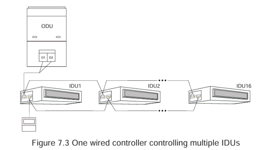
Correct VRF D1-D2 daisy-chain communication arrangement.
Back to top - Table of Contents
120Ω Communication Resistor
Each VRF system requires a terminating resistor.
Install the supplied 120Ω resistor:
Across:
D1 and D2
On:
The last indoor unit in the communication network
If a central controller is installed:
Install an additional resistor across:
G1 and G2
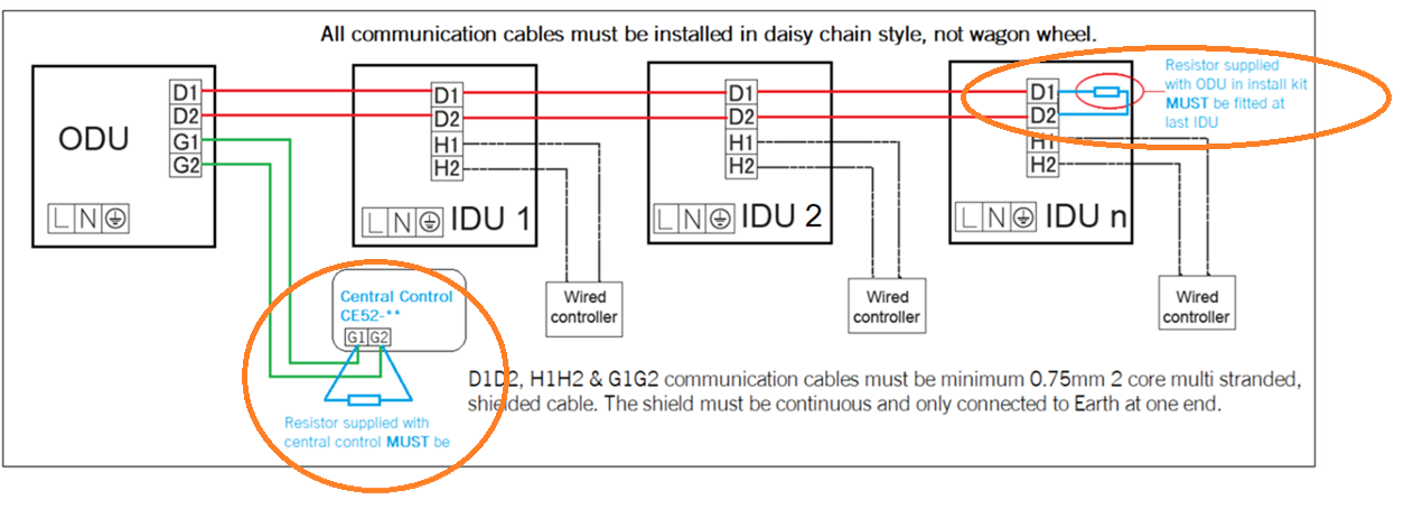
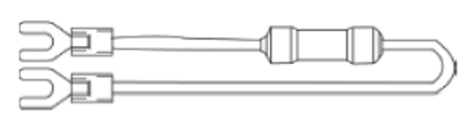
120Ω resistor installation on the final indoor unit.
Back to top - Table of Contents
Refrigerant Requirements
Commissioning will fail if insufficient refrigerant has been added.
Before commissioning:
✅ Additional refrigerant calculated
✅ Additional refrigerant added
✅ Pressure test complete
✅ Vacuum complete
✅ Minimum 70% of calculated refrigerant added
Common result:
U4 – Refrigerant Shortage
Back to top - Table of Contents
Y-Branch Installation
Incorrect Y-Branch installation can cause:
- U8 faults
- Poor performance
- Failed commissioning
Requirements:
✅ Installed within ±30°
✅ Insulated
✅ Supported correctly
✅ Minimum 500 mm straight pipe
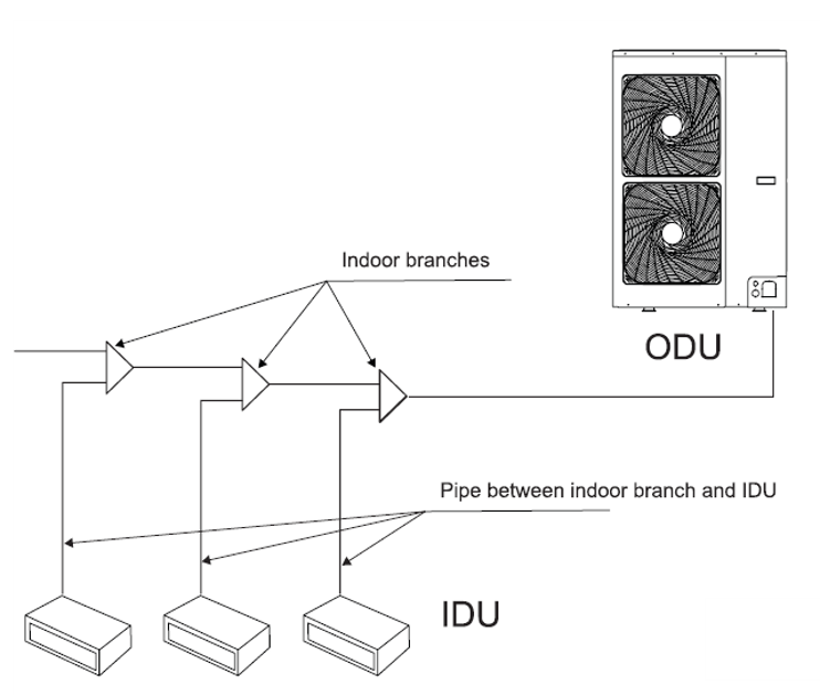
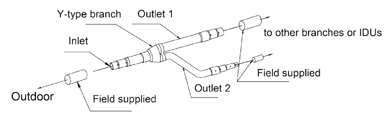
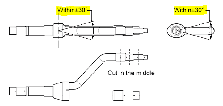
Correct Y-Branch installation requirements.
Back to top - Table of Contents
Start Commissioning
Step 1
Confirm all displays show:
A0
Step 2
Configure one outdoor unit as:
MASTER UNIT
Only one master unit is permitted.
Step 3
Locate outdoor unit displaying:
01
Step 4
Press and hold:
SW7
For approximately:
5 seconds
The outdoor unit enters debugging mode.
Back to top - Table of Contents
Debugging Sequence
The system automatically performs the following checks:
| Step | Function |
|---|---|
| 01 | Master unit verification |
| 02 | Address allocation |
| 03 | Outdoor quantity check |
| 04 | Indoor quantity check |
| 05 | Communication test |
| 06 | Outdoor component test |
| 07 | Indoor component test |
| 08 | Compressor preheat check |
| 09 | Refrigerant level check |
| 10 | Valve status check |
| 11 | Refrigerant verification |
| 12 | Final startup confirmation |
| 15 | Cooling debug |
| 16 | Heating debug |
| 17 | Completion |
Back to top - Table of Contents
Technician Action Required During Commissioning
Step 03 – Outdoor Quantity
System displays number of outdoor units detected.
Verify quantity matches installation.
Press:
SW7
to continue.
Back to top - Table of Contents
Step 04 – Indoor Quantity
System displays number of indoor units detected.
Verify quantity matches installation.
Press:
SW7
to continue.
If quantity is incorrect:
Check:
- Indoor power.
- Communications.
- Resistor.
- Wiring polarity.
Back to top - Table of Contents
Commissioning Fault Codes & Corrective Actions
CC
No Master Outdoor Unit
Check:
- Master unit selection.
Back to top - Table of Contents
CF
Multiple Master Units
Check:
- Only one master unit configured.
Back to top - Table of Contents
L7
No Master Indoor Unit
Check:
- Indoor communications.
- Indoor power.
Back to top - Table of Contents
C2
Compressor Communication Fault
Check:
- Compressor inverter wiring.
- PCB connections.
Back to top - Table of Contents
C3
Fan Communication Fault
Check:
- Fan wiring.
- Outdoor PCB.
Back to top - Table of Contents
CH
Indoor Capacity Too High
Check:
- Indoor unit selections.
Back to top - Table of Contents
CL
Indoor Capacity Too Low
Check:
- Indoor unit selections.
Back to top - Table of Contents
U0
Compressor Not Preheated
Check:
- Outdoor unit powered for minimum 8 hours.
Back to top - Table of Contents
U4
Insufficient Refrigerant
Check:
- Refrigerant charge.
- Leaks.
- Refrigerant calculations.
Back to top - Table of Contents
U6
Outdoor Valves Not Open
Check:
- Liquid valve.
- Gas valve.
- Oil balancing valves.
Back to top - Table of Contents
U8
Indoor Pipework Fault
Check:
- Y-Branches.
- Pipe sizing.
- Pipe routing.
- Crossed pipework.
Back to top - Table of Contents
U9
Outdoor Pipework / Valve Fault
Check:
- Outdoor pipework.
- Service valves.
- Oil balance valves.
Back to top - Table of Contents
Most Common Commissioning Failures
- Missing 120Ω resistor.
- Communication wiring not daisy chained.
- Indoor units not powered.
- Refrigerant not added.
- Outdoor powered less than 8 hours.
- Closed service valves.
- Incorrect indoor count detected.
- Star-wired communications.
- Crossed refrigerant pipework.
- Incorrect master unit setup.
Back to top - Table of Contents
Successful Commissioning
Commissioning is complete when the outdoor unit displays:
This indicates:
✅ The commissioning (debugging) process completed successfully
✅ All indoor and outdoor units were detected correctly
✅ Communication checks passed
✅ Refrigerant and valve status checks were completed
✅ No commissioning faults were detected
✅ The system has returned to standby mode and is ready for normal operation
Important: Successful commissioning does not replace a final operational check. After commissioning, operate the system and confirm all indoor units, controllers, cooling and heating functions are operating correctly before leaving site.
Technician Sign-Off Checklist
Installation
☐ Pipework complete
☐ Drainage complete
☐ Controls installed
☐ Communication wiring complete
☐ Resistor fitted
Refrigeration
☐ Pressure tested
☐ Vacuum below 500 microns
☐ Refrigerant added
☐ Service valves opened
Power
☐ Indoor units powered
☐ Outdoor unit powered minimum 8 hours
☐ A0 displayed
Commissioning
☐ Outdoor quantity confirmed
☐ Indoor quantity confirmed
☐ OF OF displayed
☐ Cooling tested
☐ Heating tested
Handover
☐ Customer instructed on operation
☐ Warranty registration completed
Back to top - Table of Contents