⚠️ Safety Notice – Reverse Cycle Air Conditioners
This equipment must only be installed, commissioned, serviced and repaired by suitably qualified and licensed personnel.
Before commencing work, complete a task-specific risk assessment and ensure electrical isolation procedures, safe access, adequate service clearances and appropriate PPE have been considered. All work must comply with applicable regulations, standards and manufacturer requirements.
Particular care must be taken when working around electrical systems, refrigerant circuits, moving parts, roof spaces, ceiling spaces, confined spaces and working-at-heights hazards where applicable.
Do not proceed if safe access, required clearances, confined space risks or appropriate safety controls cannot be achieved and maintained.
Safety takes priority over diagnosis, repairs, installation schedules and customer expectations. If the task cannot be completed safely, it must not proceed until the risks have been adequately controlled.
68-page Pdf with table of contents chapter links attached
Summary: Complete list of models covered, important specs, pairing rules, error codes, commissioning notes and Wi‑Fi/controls for Braemar residential wall‑split, ducted, cassette, multi, and add‑on cooling systems.
Wall Split (R410A): LSHV/LCHV
Indoor: LSHV20/25/35/50/60/70/80D1S
Outdoor: LCHV20/25/35/50/60/70/80D1S
Headline specs (range overview)
- Cooling 2.02–8.20 kW; Heating 2.62–8.80 kW
- Pipe sizes: Liquid 1/4"; Gas 3/8" (up to 50) / 1/2" (50) / 5/8" (60–80)
- Refrigerant piping (typical): Pre‑charge 10 m; max length 15–25 m; max lift ~10 m
- Features: IDU Wi‑Fi, ODU DRED (RJ45); IR remote YAC1FB9; optional wired XK76
Wall Split (R32 Ultimate): KSHV/KCHV
Indoor: KSHV25/35/46/52/60/70/80/90D1S
Outdoor: KCHV25/35/46/52/60/70/80/90D1S
Headline specs (range overview)
- Cooling 2.5–9.4 kW; Heating up to 10.3 kW
- Pipe sizes: Liquid 1/4"; Gas 3/8" (25–35) / 1/2" (46–80) / 5/8" (70–90)
- Features: IDU Wi‑Fi; ODU DRED (RJ45); IR remote YAC1FB4/YAC1FB9; optional wired XK76
Wall Split (R32 Airvolution S): WSHV‑S/WCHV
Indoor: WSHV25/35/50/70D1S
Outdoor: WCHV25/35/50/70D1S
Important pairing rule:
WSHV‑S indoor units do NOT pair with WCHV‑T outdoor units. Cross pairing will trigger E6 Communication Error. Pair S with S only.
Headline specs (range overview)
- Cooling 2.5–7.0 kW; Heating 3.0–6.8 kW
- Pipe sizes: Liquid 1/4"; Gas 3/8" (25–35) / 1/2" (50) / 5/8" (70)
- Features: IDU Wi‑Fi; ODU DRED (RJ45)
Wall Split (R32 Airvolution T): WSHV‑T/WCHV
Indoor: WSHV25/35/50/70/85D1T
Outdoor: WCHV25/35/50/70/85D1T
Pairing: T with T only (do not mix with S).
Headline specs (range overview)
- Cooling 2.5–8.5 kW; Heating 3.0–9.0 kW
- Pipe sizes: Liquid 1/4"; Gas 3/8" (25–35) / 1/2" (50) / 5/8" (70–85)
- Features: IDU Wi‑Fi; ODU DRED (RJ45)
Ducted (R410A): SDHV/SCHV
Indoor (single phase): SDHV07/10/12/14/16D1S
Outdoor (single phase): SCHV07/10/12/14/16D1S
Indoor (three phase): SDHV20/24D1S
Outdoor (three phase): SCHV20/24D3S
Headline specs (range overview)
- Capacity 7–24 kW; ESP ranges 0–200/250 Pa (by model)
- Connections: Brazed (ducted); typical liquid 3/8", gas 5/8"–3/4" (by size)
- Controllers: XK60/XK75 (1φ), XK46 (3φ)
- Notes: Detailed 3‑phase commissioning below
Ducted (R32): KDHV/KCHV
Indoor: KDHV070/100/125/140/160D1S
Outdoor: KCHV070/100/125/140/160D1B
Headline specs (range overview)
- Cooling 7.1–16.3 kW; Heating up to 18.6 kW
- Built‑in drain pump (IDU); ESP 25–50 Pa
- Wi‑Fi: ME31‑00/C6 module; Zone control compatible (see kit)
Cassette (R410A): SBHV/SCHV
Indoor: SBHV07/10/12/14D1S (fascia TC04/TC05)
Outdoor: SCHV07/10/12/14D1S
Headline specs (range overview)
- 7–14 kW; airflow 385–635 L/s
- Connections: Brazed; panel sizes and SPL per model
- Controls: IR YB1FA; optional wired XK75
Cassette (R32): KBHV/KCHV
Indoor: KBHV070/100/125/140D1S (fascia TF06)
Outdoor: KCHV070/100/125/140D1B
Headline specs (range overview)
- 7.1–13.6 kW (IDU airflow 389–611 L/s)
- Controls: IR YAP1F6; wired XE71‑42G
- Notes: 1‑phase outdoor power; pipe sizes and SPL as specified
Multi Split (R410A): MCHV + compatible indoors
Outdoor: MCHV54D12 / 73D13 / 81D14 / 10D14 / 11D15
Max IDUs: 2 / 3 / 4 / 4 / 5 (by model)
Compatible indoor families
- High Wall: LSHV, BSHV, KSHV
- Bulkhead: MDHV
- Cassette: MBHV
- Hi‑Wall Airvolution: WSHV‑S / WSHV‑T (match variants correctly)
Notes: DRED as standard; combination tables available.
Multi Split (R32): NCHV + compatible indoors
Outdoor: NCHV53D12 / 72D13 / 80D14 / 10D14
Max IDUs: 2 / 3 / 4 / 4 (by model)
Compatible indoor families
- Bulkhead: NDHV
- Cassette: NBHV
- Hi‑Wall: WSHV‑S / WSHV‑T (match S/T correctly)
Combination tables: Provided for 2–4 IDUs (see Multi Combination article, or contact Tech Support).
Bulkhead (R410A): MDHV
Indoor: MDHV25/35/50/60/70D1S
Headline specs (range overview)
- Cooling 2.5–7.1 kW; Heating 2.8–8.0 kW
- Airflow 125–278 L/s; SPL bands 31–42 dB(A)
- Pipe sizes: Liquid 1/4" (25–60), 3/8" (70); Gas 3/8" (25–35), 1/2" (50), 5/8" (60–70)
Bulkhead (R32): NDHV
Indoor: NDHV25/35/50/70D1S
Headline specs (range overview)
- Cooling 2.65–7.0 kW; Heating 2.8–8.0 kW
- Airflow 105–417 L/s; ESP nominal 25 Pa (up to 125 Pa on 70)
- Pipe sizes: Liquid 1/4"; Gas 3/8" (25–35), 1/2" (50), 5/8" (70)
Cassette (R410A small): MBHV
Indoor: MBHV35/45/71D1S (panels TA03/TB04)
Headline specs (range overview)
- Cooling 3.5–7.1 kW; Heating 4.0–8.0 kW
- Panel sizes 670×670×50 (35/45) / 950×950×60 (71)
- Pipe sizes: Liquid 1/4" (35/45), 3/8" (71); Gas 3/8" (35), 1/2" (45), 5/8" (71)
Cassette (R32 small): NBHV
Indoor: NBHV35/45/71D1S (panels TC03/TC04)
Headline specs (range overview)
- Cooling 3.5–7.1 kW; Heating 4.0–8.0 kW
- Panel sizes 670×670×50 (35/45) / 950×950×60 (71)
- Pipe sizes: Liquid 1/4" (35/45), 3/8" (71); Gas 3/8" (35), 1/2" (45), 5/8" (71)
Add‑On Cooling (R410A): SACV + Braemar DGH XA matching
Indoor: SACV10/12/14/16D1S
Outdoor: SCHV10/12/14/16D1S
Headline specs (range overview)
- Nominal cooling 10.0 / 13.0 / 14.5 / 15.5 kW
- Matched DGH XA (MagIQTouch):
- SACV10: X20, X23 → Transition 645513 (946×290 to Ø400)
- SACV16: X30, X32 → Transition 645520 (1110×290 to Ø450)
- Sensible capacities & airflow bands per model in guide
Add‑On Cooling (R32): KACV + Braemar DGH XA matching
Indoor: KACV125/140/160D1S
Outdoor: KCHV125/140/160D1B
Headline specs (range overview)
- Nominal cooling 11.2 / 12.65 / 16.0 kW
- Matched DGH XA (MagIQTouch):
- KACV125: X20, X23 → Transition 645513
- KACV160: X30, X32 → Transition 645520
- Dehumidifying volumes, airflow bands and pipe sizes per model in guide
Controls, Gateways & Zone Control
Wall/Ducted Controllers
- XK60 / XK75 / XE71 (single phase)
- XK46 (3‑phase SDHV; also as secondary controller for primary/secondary setups)
Gateways
- ME30‑42/E1 — Dry Contact Gateway (remote I/O: on/off, mode, error output, etc.)
- ME50‑00/EG(M) — Modbus Gateway (for connection to central controllers like CE52‑24/F(C))
Wi‑Fi Modules
- ME31‑00/C6 — KDHV/KCHV series
- ME31‑00/C13 — Zone Control system (LE60‑13/GH‑KIT)
Zone Control (Inverter Ducted)
- LE60‑13/GH‑KIT — Includes XE70‑13/E color UI, 4× RF remotes LE60‑13/C1, Zone Control Interface, transformer & cables
- Supports SDHV (R410A) single & three‑phase and KDHV (R32) single‑phase
- Installation & commissioning steps provided (connect H1/H2, RS485/HBS, damper ports, antenna, power, optional Wi‑Fi module)
Commissioning (SDHV 3‑phase)
LED1 / SW3 Flow (summary)
- LED1 → “AO” (waiting for commissioning)
- Press & hold SW3 ~10 s to start; display alternates “01” ↔ “03”; press SW3 while “03” shows to confirm
- System self‑diagnostics until “08”; press SW3 to confirm pre‑heat satisfied
- “09” — checks ODU fan motors & compressor (≈3–5 min)
- Alternates “01” ↔ “0F” → commissioning complete
- Operate from wired controller; verify airflow settings & refrigerant charge
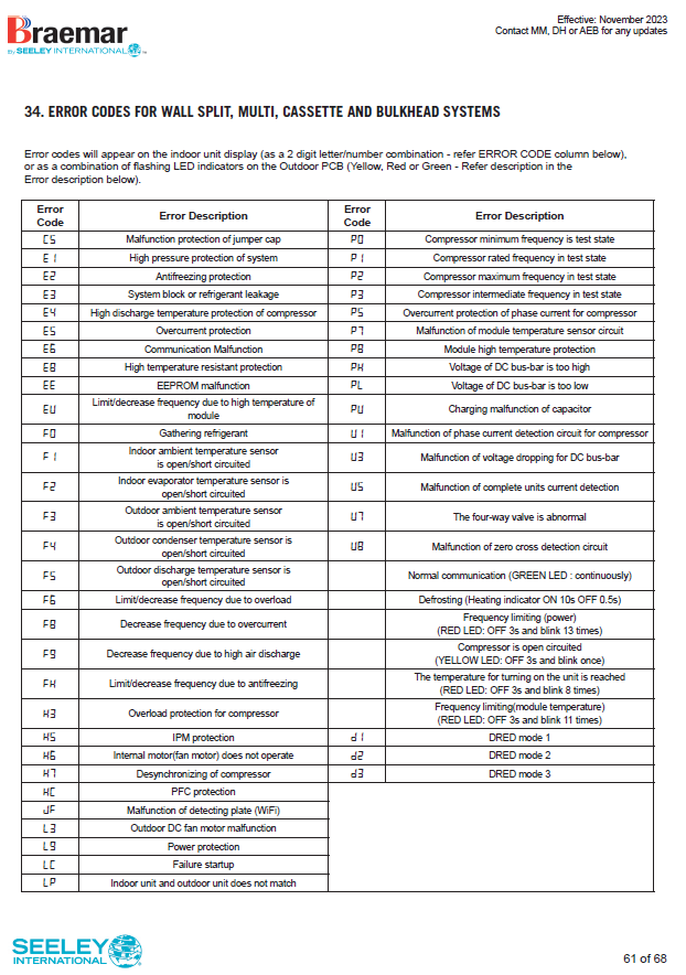
Error Codes (Splits/Multi/Cassette/Bulkhead)
Common faults
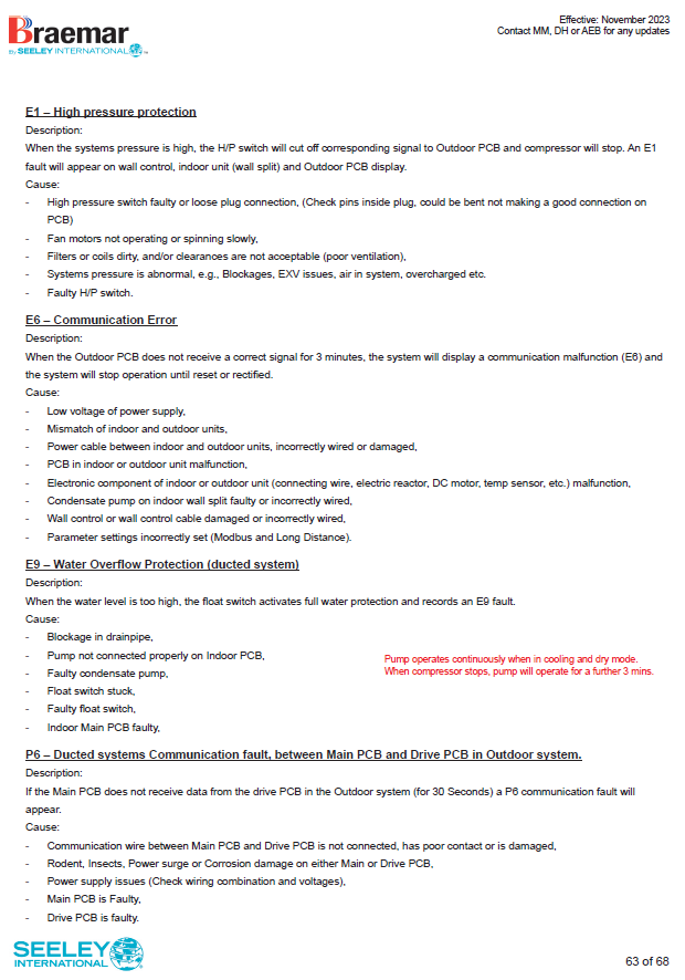
E1 – High Pressure Protection
Description:
System shuts down when refrigerant pressure is too high. Error appears on wall control, indoor unit, and outdoor PCB.
Causes:
- High-pressure switch faulty or loose plug connection (check pins inside plug; bent pins can cause poor contact).
- Outdoor fan not operating or spinning slowly.
- Dirty filters or coils; poor ventilation around outdoor unit.
- Refrigerant issues: blockages, EXV malfunction, air in system, or overcharge.
Action:
- Clean coils and filters; ensure clear airflow.
- Check fan operation and clearances.
- Test refrigerant pressures and EXV.
- Inspect high-pressure switch and wiring.
E6 – Communication Error
Description:
Outdoor PCB does not receive correct signal for 3 minutes; system stops until reset or fault cleared.
Causes:
- Low or unstable power supply.
- Indoor/outdoor unit mismatch (e.g., WSHV‑S ≠ WCHV‑T).
- Damaged or incorrectly wired comm cable.
- PCB fault in indoor or outdoor unit.
- Faulty electronic components (reactor, motor, sensors).
- Condensate pump wiring fault on wall splits.
- Incorrect parameter settings (Modbus / Long Distance).
Action:
- Confirm correct model pairing.
- Check voltage at isolator.
- Inspect comm wiring and wall control cable.
- Test PCBs and reset system.
E9 – Water Overflow (Ducted Systems)
Description:
Float switch activates when water level is too high; system stops and displays E9.
Causes:
- Blocked drain line.
- Pump not connected properly to indoor PCB.
- Faulty pump or float switch.
- Indoor main PCB fault.
Action:
- Clear drain line.
- Check pump wiring and float switch.
- Replace faulty components.
(Note: Pump runs continuously in cooling/dry mode; after compressor stops, pump runs for 3 mins.)
P6 – PCB Communication Fault (Ducted)
Description:
Main PCB and Drive PCB in outdoor unit fail to communicate for 30 seconds.
Causes:
- Loose or damaged comm cable.
- Rodent/insect damage or corrosion on PCB.
- Power supply issues.
- Faulty main or drive PCB.
Action:
- Inspect comm cable and connectors.
- Check PCBs for damage.
- Verify voltage and wiring.
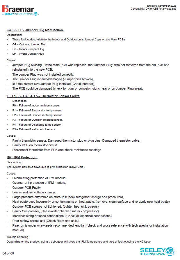
C4 / C5 / LP – Jumper Plug Errors
Ensure jumper cap is present, correct size, and fitted properly. Transfer jumper from old PCB when replacing.
F0–F5 – Sensor Faults
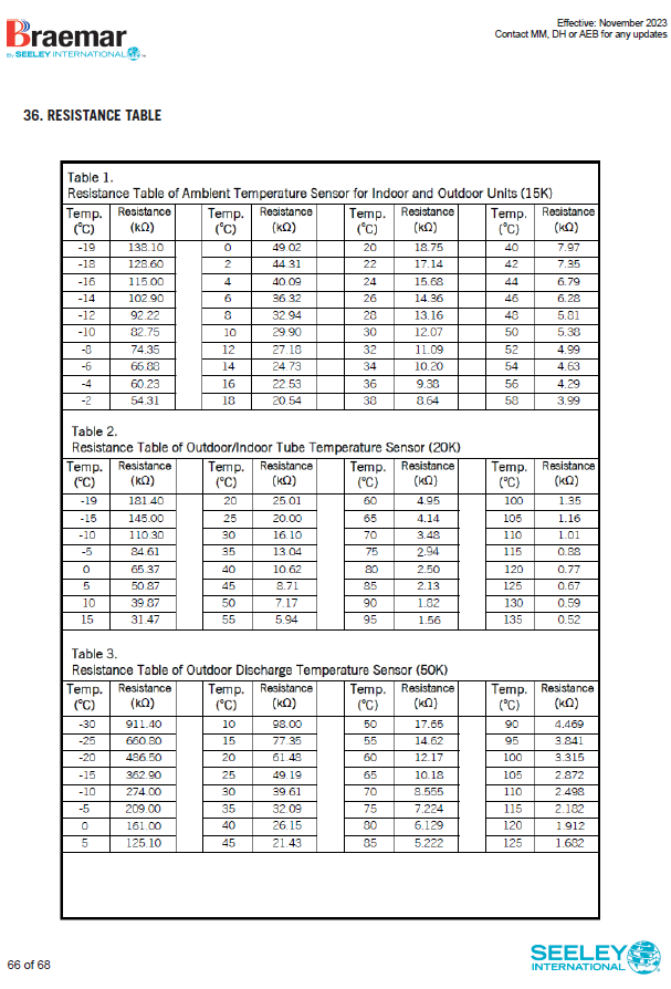
Inspect thermistor plugs and harness; measure resistance against spec; replace faulty sensor or PCB.
H5 – IPM Protection
Inverter module shut down due to overheat or overcurrent.
Check heat sink screws and thermal paste; inspect airflow and coil condition; verify voltage stability and compressor health.
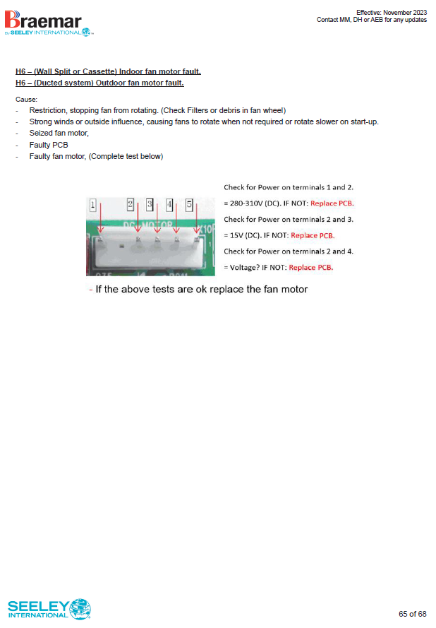
H6 – Fan Motor Fault
Indoor or outdoor fan motor not operating correctly.
Remove obstructions/debris; check for seized bearings; test motor windings and PCB output.
Tip: Full error code tables (including P-codes, U-codes, PH/PL) and LED patterns for outdoor PCBs are in the service guide.
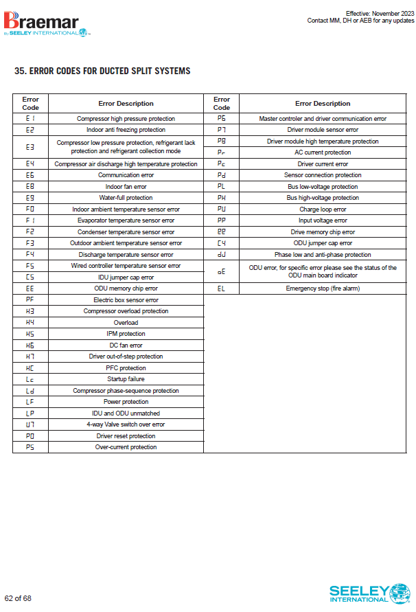
Error Codes (Ducted Systems: SDHV/KDHV)
Additional ducted highlights
- E9 — Water overflow (IDU): Drain blockage, pump connection at PCB, faulty pump/float, float stuck, main PCB fault
- P6 — ODU Main ↔ Drive PCB comms: Check inter‑board comms cable, rodent/insect/surge/corrosion damage, supply stability, main/drive PCB integrity
⚠️ Error Codes “E” – System Protection & Communication
E0 – Water Pump / Voltage Protection
Indicates water pump faults (drain overflow or weak start-up current). The compressor and fan may halt ~3 minutes later. Check pump and float; verify supply voltage.E1 – High‑Pressure Protection
Triggered by: blocked outdoor coil, refrigerant overcharge, restricted flow, or faulty high-pressure switch. Inspect condenser, airflow, and pressure switch.E2 – Freeze / Low‑Temperature Protection
Indoor coil icing or frozen line detect. Check for low refrigerant or blocked airflow.E3 – Low‑Pressure Protection
Caused by refrigerant undercharge/leak or dirty filters. Check charge levels and pressure switch.E4 – Compressor Discharge Over‑Temp
Discharge line overheating; detected by PCB. May auto shutdown after repeats. Check discharge line temperature and airflow.E5 – Over‑Current / Voltage Fluctuation
Triggered by unstable power or voltage out-of-range. Check supply, wiring, and electrical stability.E6 – Indoor ↔ Outdoor Communication Failure
One of the most common codes. Probable causes: loose/damaged communication wires, faulty control boards, mismatched unit pairing (e.g., S vs T models). Reset power, inspect wiring/PCB, ensure correct model pairing.E7 – Mode Conflict
Indoor and outdoor units set to opposing modes (e.g., heating vs cooling). Sync the mode, then reset the system.E8 – Indoor Fan Motor or PCB Fault
Indicates indoor fan motor issues or PCB failure. Check fan motor connection, operation, and indoor PCB.E9 – Water‑Pump / Tray Overflow
Specific to units with drain pumps. Check pump, float switch, tray levels.
Error Codes “F” – Sensor Faults
Often require component replacement; check sensor resistance and connections first.
| Code | Function |
|---|---|
| F0 | Indoor ambient temp sensor (20 kΩ) |
| F1 | Indoor evaporator pipe sensor (25 kΩ) |
| F2 | Outdoor condenser sensor (50 kΩ) |
| F3 | Outdoor ambient sensor (20 kΩ) |
| F4 | Outdoor discharge tube sensor (25 kΩ) |
| F5 | Controller/wired sensor |
Error Codes “H” – Heating & High-Temperature Protection
- H0 – Heating tube high temperature
- H1 – Defrost mode/status, not an error
- H2 – Static de-dusting (filter maintenance)
- H3 – Compressor overload
- H4 – Evaporator/condenser overload
- H5 – IPM protection (power module fault; shutdown on overcurrent/temperature)
- H6 – Outdoor fan motor failure or IPM overheat
- H7 – Compressor maloperation
- H8 – Dehumidification tray full or IPM overheating for fan
- H9 – Loss of fan synchronization
Error Codes “P” – Motherboard & Drive Communication
- P0 – Drive module reset failure
- P5 – Compressor current protection
- P6 – Communication error between main and drive PCB
- P7 – OFC IC temperature sensor fault
- P8 – PFC IC over-temperature error
Error Codes “C” & “U” – Jumpers and Power Issues
- C5 – Jumper cap missing or incorrectly installed on PCB
Ensure proper jumper transferred on PCB replacement. - U-codes (e.g., U1, U2, U3…) – Likely CPU EEPROM faults, phase current issues, voltage drop, compressor demagnetization.
Inspect PCB/modules.
Recommended Troubleshooting Workflow
Power Reset & Observe
- Turn the unit OFF at the isolator or breaker for 2–3 minutes, then restart.
- Watch if the error code reappears—this rules out temporary glitches.
Check Wiring & Connections
- Inspect communication cables between indoor and outdoor units (especially for E6 errors).
- Look for loose plugs, damaged insulation, or corroded terminals.
- Confirm sensor plugs (F-series codes) are firmly seated and not broken.
- Verify jumper caps on PCBs (C5 codes)—they must be in the correct position.
Check Refrigerant & Coil Conditions
- For E1–E4(pressure or temperature faults):
- Clean indoor and outdoor coils.
- Check airflow (filters, fan operation).
- Connect gauges and confirm suction/discharge pressures match spec.
- Look for signs of overcharge or leaks.
- For E1–E4(pressure or temperature faults):
Electrical Health Check
- For E5, H5, P-series:
- Measure supply voltage at the isolator—should be stable within spec.
- Check current draw on compressor and fan motors.
- Inspect inverter module heat sink and ensure screws are tight (IPM protection).
- Look for burnt marks or swelling on capacitors.
- For E5, H5, P-series:
Confirm Correct Pairing & Mode
- Ensure indoor and outdoor units are matched models (e.g., S-series indoor with S-series outdoor).
- If E7 appears, both units must be in the same mode (cooling or heating).
- Reset mode conflicts by turning both units OFF, then reselect the correct mode.