12V DC to 24V AC Retrofit iCPMD Kit – Installation (Drain Valve, Solenoid & iCPMD) - 865512-B Literature
Kit: P/No. 123226 / 123233
Applies to: LCQi, LPQi, TBSi, TBQi (Inverter models only)
Summary
This procedure outlines installation of the 24V AC retrofit iCPMD kit, replacing legacy 12V DC components:
- Solenoid Valve – P/No. 834320
- Drain Valve – P/No. 107714
- Water Sensor – P/No. 833699
- iCPMD Box – P/No. 122694 (230V variant referenced)
Commissioning must be completed using Installation Manual P/No. 865208 (start at water level setup).
⚠️ Critical Safety & Warnings
- Isolate mains power and water before starting work.
- Turn electronics module isolator OFF before disconnecting or reconnecting components.
- Licensed technicians only.
Product Compatibility (Critical)
- ✅ Only for inverter models: LCQi, LPQi, TBSi, TBQi
- ❌ Do NOT install on non‑inverter units
- Will cause Fault Code 7
- May damage fan and motor collet
Procedure
1. Remove Electronics Module
- Turn isolator OFF and isolate power + water.
- Remove screw under isolation switch.
- Lift module clear of mounting stand.

- Disconnect:
- Motor plug
- All peripheral connections (refer Fig. 7)
2. Replace Solenoid Valve (P/No. 834320 – 24V AC)
✅ Important updates from B version applied
- Retain existing float valve assembly
- Replace solenoid only

Key installation points:
- Confirm 24V AC solenoid (834320) is used
- Ensure flow direction arrow is correct
- Ensure all washers are fitted
- ❌ No thread tape required
- Tighten until sealed (do not overtighten)
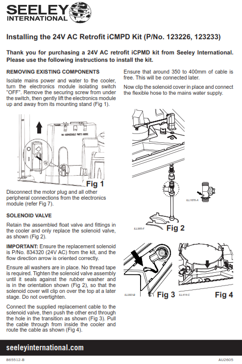
Cable routing:
- Connect supplied cable
- Feed through transition opening
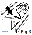
- Route internally as per layout

- Leave 350–400 mm free cable
Finish:
- Clip solenoid cover on
- Connect flexible hose to mains water
3. Replace Drain Valve (P/No. 107714 – 24V AC)
- Remove existing 12V DC valve
- Assemble new valve as per kit

Critical requirements:
- Confirm correct part: 107714 (24V AC)
- Fit O-ring before installation
- Tighten nut by hand underneath cooler
Drain compliance:
- Must discharge to approved drainage point
- ❌ Do NOT drain onto roof surface
4. Replace Water Sensor (P/No. 833699)
- Remove existing sensor
- Clip new sensor onto tank

Key checks:
- Confirm correct part: 833699
- Ensure clip is fully engaged
- Route cable through tank supports
- Leave connector clear of water
5. Replace iCPMD Box & Reconnect Wiring
- Replace old 12V DC iCPMD with:
- P/No. 122694 (230V) or kit equivalent
Reconnect:
Motor cable → base of electronics module
- Polarised connector
- Ensure retention clips engage
Wall controller cable:
- Route via same channel
- Leave ~200 mm outside cavity
6. Reassemble Electronics Module
- Refit module to tank
- Reinstall securing screw
⚠️ Important:
- Isolation switch will NOT operate without this screw installed
7. Reconnect Accessories (Fig. 7 Layout)

With electronics module OFF:
✅ Remain the same:
- Pump
- Motor
- Wall control
? Change positions:
- Water probe
- Drain valve
- Solenoid
Commissioning & Final Checks
- Follow Installation Manual P/No. 865208
- Start at water level setup (commissioning section)
Final checks:
- Test full operation
- Check all connections
- Inspect for leaks
- Confirm correct cable routing
- Refit pad frames
- Explain operation to customer
⚠️ Critical Installation Checks (Often Missed)
- Cables must not sit in water once tank is filled
- All connectors must be:
- Correct orientation
- Fully seated (per Fig. 7)
Troubleshooting
Fault Code 7
Cause:
- Installed on non-inverter unit
Action:
- Remove kit
- Inspect fan & motor collet for damage
Isolation Switch Not Working
Cause:
- Mounting screw not installed
Action:
- Refit securing screw to enable switch
Water / Electrical Issues
Cause:
- Incorrect cable routing or orientation
Action:
- Re-route cables above water level
- Confirm wiring matches Fig. 7 layout