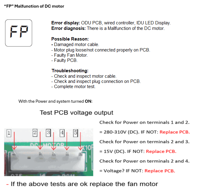
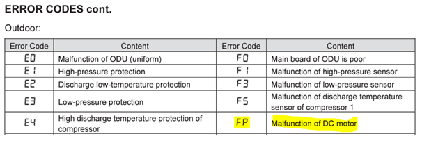
FP Fault Code – VRF Systems (Outdoor DC Fan Motor Fault)
⚠️ Safety Notice – Reverse Cycle Air Conditioners
This equipment must only be installed, commissioned, serviced and repaired by suitably qualified and licensed personnel.
Before commencing work, complete a task-specific risk assessment and ensure electrical isolation procedures, safe access, adequate service clearances and appropriate PPE have been considered. All work must comply with applicable regulations, standards and manufacturer requirements.
Particular care must be taken when working around electrical systems, refrigerant circuits, moving parts, roof spaces, ceiling spaces, confined spaces and working-at-heights hazards where applicable.
Do not proceed if safe access, required clearances, confined space risks or appropriate safety controls cannot be achieved and maintained.
Safety takes priority over diagnosis, repairs, installation schedules and customer expectations. If the task cannot be completed safely, it must not proceed until the risks have been adequately controlled.
Applies To
- Braemar / VRF Systems
- Outdoor Units (all VRF series using DC fan motors)
Fault Description
The FP fault code is displayed on:
- Indoor wired controller
- Indoor display / receiver board
- Outdoor main PCB
Indicates a fault with the outdoor DC fan motor or associated control circuitry.
Possible Causes
- Outdoor fan blade obstructed or seized
- Damaged or burnt-out DC fan motor
- Fan motor wiring damage / disconnection
- Poor connection at PCB terminals
- Faulty outdoor main PCB
- No motor drive signal from PCB
The outdoor unit contains high voltage components (up to ~350V DC) and moving parts. Failure to follow correct testing procedures may result in electric shock, equipment damage, or personal injury. Ensure safe isolation practices are followed, and only qualified personnel carry out diagnostic checks.
Step-by-Step Troubleshooting
1. Visual Inspection
- Check outdoor fan operation:
- Ensure fan rotates freely - must rotate smoothly and without restriction
- Remove any debris or obstruction
YouTube Video: Checking Outdoor Fan Rotates Smoothly
- Remove fan blade and:
- Inspect for damage
- Spin motor shaft – must rotate smoothly
- Inspect for motor overheating:
- Burnt motors may show yellow discoloration
2. Wiring & Connection Checks
- Inspect fan motor cable for:
- Cuts, abrasion, or rubbing from fan blade
- Check all plugs:
- Fully seated into outdoor PCB
- No loose or bent pins
- Inspect PCB terminals for damage
3. Electrical Testing (DC Fan Motor Circuit)
⚠️ Use a multimeter and follow safe electrical practices
Set Multimeter to DC Voltage
| Test | Terminals | Normal Value |
|---|---|---|
| Motor Supply (Vdc) | Red ↔ Black | 232V – 356V DC |
| Driver Voltage (Vcc) | White ↔ Black | 0 – 15V DC |
| Speed Signal (Vsp) | Yellow ↔ Black | 2.1V – 6.5V DC |
- Important:
- Vcc above 15V may damage the PCB
Set Multimeter to AC Voltage
- Check incoming supply to outdoor PCB:
- Normal: 165V – 253V AC
Set Multimeter to Frequency (Hz)
- Check motor feedback signal:
- Terminals: Blue ↔ Black
- Formula:
Fan Speed (RPM) = Frequency × 5
Diagnosis Guidelines
If ALL values are normal:
- Vdc, Vcc, Vsp, supply voltage and feedback signal are within range
- BUT fan does not run or stops:
Conclusion:
- Internal motor protection likely activated
- Fan motor is faulty (burnt out) and must be replaced
❌ If Abnormal Readings Found:
| Condition | Likely Fault |
|---|---|
| No Vdc output | Faulty PCB |
| Vcc out of range | PCB or driver fault |
| No Vsp signal | Control issue (PCB) |
| No feedback signal | Motor failure or wiring fault |
| No AC supply | Power supply issue |
Recommended Actions
- Rectify any mechanical obstruction or wiring fault
- Repair/replace damaged wiring or connectors
- Replace outdoor fan motor if faulty
- Replace outdoor PCB if no drive signals present
Important Notes
- Always isolate power before inspection
- Only qualified technicians to perform live testing
- Follow local electrical safety regulations
- Refer to manufacturer service procedures where required
The outdoor unit contains high voltage components (up to ~350V DC) and moving parts. Failure to follow correct testing procedures may result in electric shock, equipment damage, or personal injury. Ensure safe isolation practices are followed, and only qualified personnel carry out diagnostic checks.