⚠️ Safety Notice – Reverse Cycle Air Conditioners
This equipment must only be installed, commissioned, serviced and repaired by suitably qualified and licensed personnel.
Before commencing work, complete a task-specific risk assessment and ensure electrical isolation procedures, safe access, adequate service clearances and appropriate PPE have been considered. All work must comply with applicable regulations, standards and manufacturer requirements.
Particular care must be taken when working around electrical systems, refrigerant circuits, moving parts, roof spaces, ceiling spaces, confined spaces and working-at-heights hazards where applicable.
Do not proceed if safe access, required clearances, confined space risks or appropriate safety controls cannot be achieved and maintained.
Safety takes priority over diagnosis, repairs, installation schedules and customer expectations. If the task cannot be completed safely, it must not proceed until the risks have been adequately controlled.
B1, B2, B3, B4, B5, B6, B7, B9, BA, BB, BE, BF, BJ, BP, BU Error Codes – VRF Temperature Sensor Malfunction (MCMX, MCSX, MCHX, MCRX)
Overview
These fault codes indicate a problem with an outdoor unit temperature sensor circuit. The fault may be caused by:
- Loose or poor sensor connections
- Damaged sensor wiring
- Failed temperature sensor
- Main control board sensor detection circuit fault
- Incorrect sensor installation or replacement
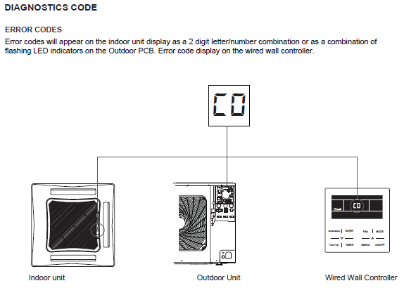
Fault Code Descriptions
| Error Code | Fault Description |
|---|---|
| B1 | Outdoor ambient temperature sensor malfunction |
| B2 | Defrost temperature sensor 1 malfunction |
| B3 | Defrost temperature sensor 2 malfunction |
| B4 | Sub-cooler liquid temperature sensor malfunction |
| B5 | Sub-cooler gas temperature sensor malfunction |
| B6 | Vapour-liquid separator inlet tube temperature sensor malfunction |
| B7 | Vapour-liquid separator outlet tube temperature sensor malfunction |
| B9 | Oil return temperature sensor 1 malfunction |
| BA | Oil return temperature sensor 2 malfunction |
| BB | Oil return temperature sensor 4 malfunction |
| BE | Condenser inlet tube temperature sensor malfunction |
| BF | Condenser outlet tube temperature sensor malfunction |
| BJ | High-pressure and low-pressure sensors connected incorrectly |
| BP | Oil return temperature sensor 2 malfunction |
| BU | Oil return temperature sensor 3 malfunction |
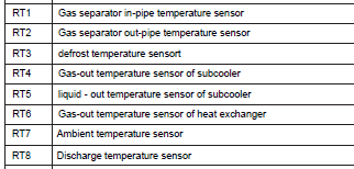
Sensor Identification
| Sensor | Function | Nominal Resistance @ 25°C |
|---|---|---|
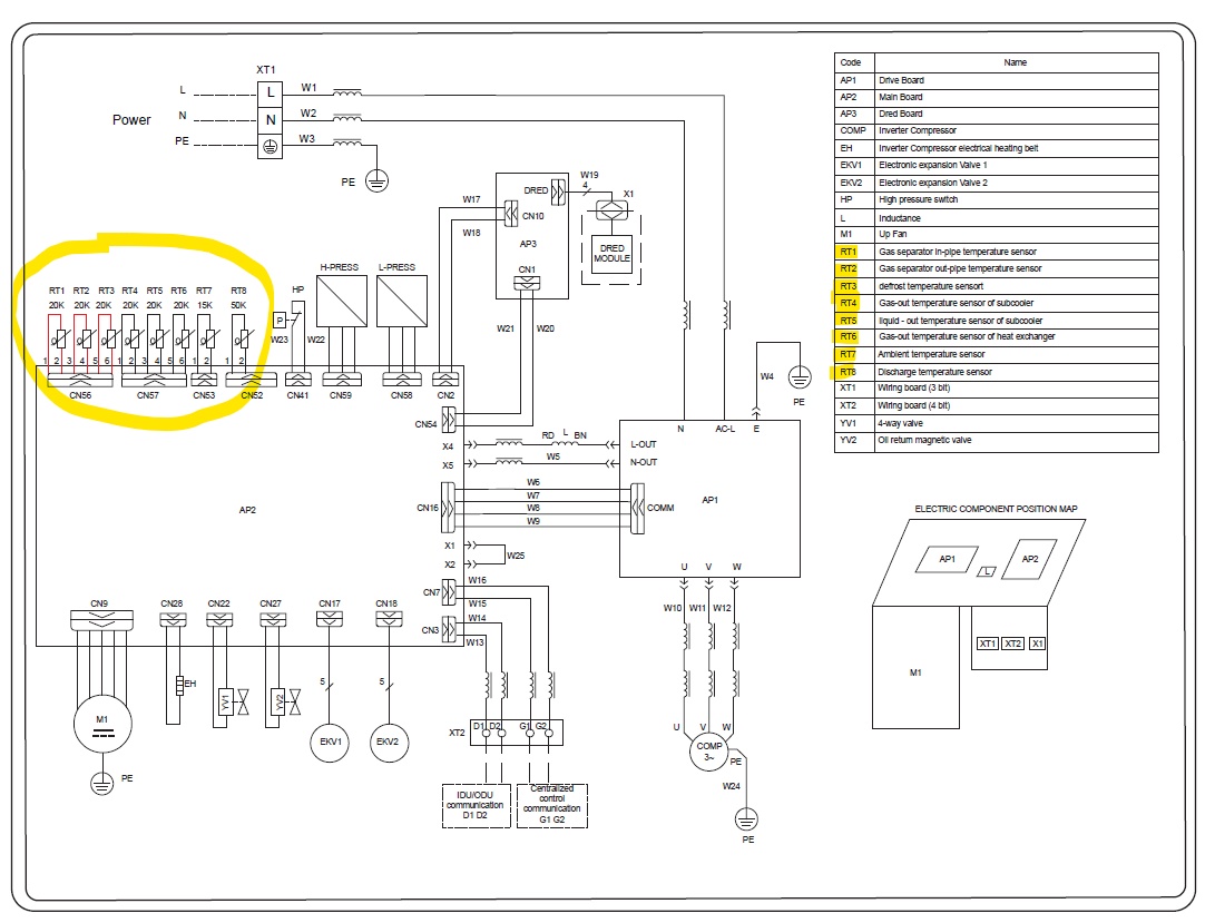
| RT1 | Gas separator in-pipe temperature sensor | 20 kΩ |
| RT2 | Gas separator out-pipe temperature sensor | 20 kΩ |
| RT3 | Defrost temperature sensor | 20 kΩ |
| RT4 | Sub-cooler gas temperature sensor | 20 kΩ |
| RT5 | Sub-cooler liquid temperature sensor | 20 kΩ |
| RT6 | Heat exchanger inlet temperature sensor | 20 kΩ |
| RT7 | Outdoor ambient temperature sensor | 15 kΩ |
| RT8 | Discharge temperature sensor | 50 kΩ |
Important: RT1 to RT6 are 20 kΩ sensors, RT7 is a 15 kΩ sensor, and RT8 is a 50 kΩ sensor. They are not interchangeable.
Diagnostic Procedure
1. Inspect Sensor Connections
- Isolate power to the outdoor unit.
- Check that the affected sensor is securely connected to the main control board.
- Inspect terminals for corrosion, moisture ingress, or loose contacts.
- Reseat any suspect connectors.
2. Inspect Sensor Wiring
- Follow the wiring from the sensor back to the control board.
- Look for:
- Damaged insulation
- Pinched or rubbed wiring
- Broken conductors
- Water ingress
- Poor repairs or joins
Repair any wiring defects before proceeding.
3. Compare Sensor Resistances
When the outdoor unit has been powered off long enough for all components to reach a similar temperature:
- Disconnect the sensor plugs from the control board.
- Measure resistance across each sensor.
- Compare readings between sensors of the same type.
Expected Results
- RT1 to RT6 should have similar resistance values because they are all 20 kΩ thermistors.
- RT7 will read differently because it is a 15 kΩ thermistor.
- RT8 will read significantly differently because it is a 50 kΩ thermistor.
A sensor with a resistance value that is substantially different from other sensors at the same temperature is likely faulty.
4. Identify the Faulty Sensor
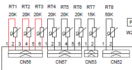
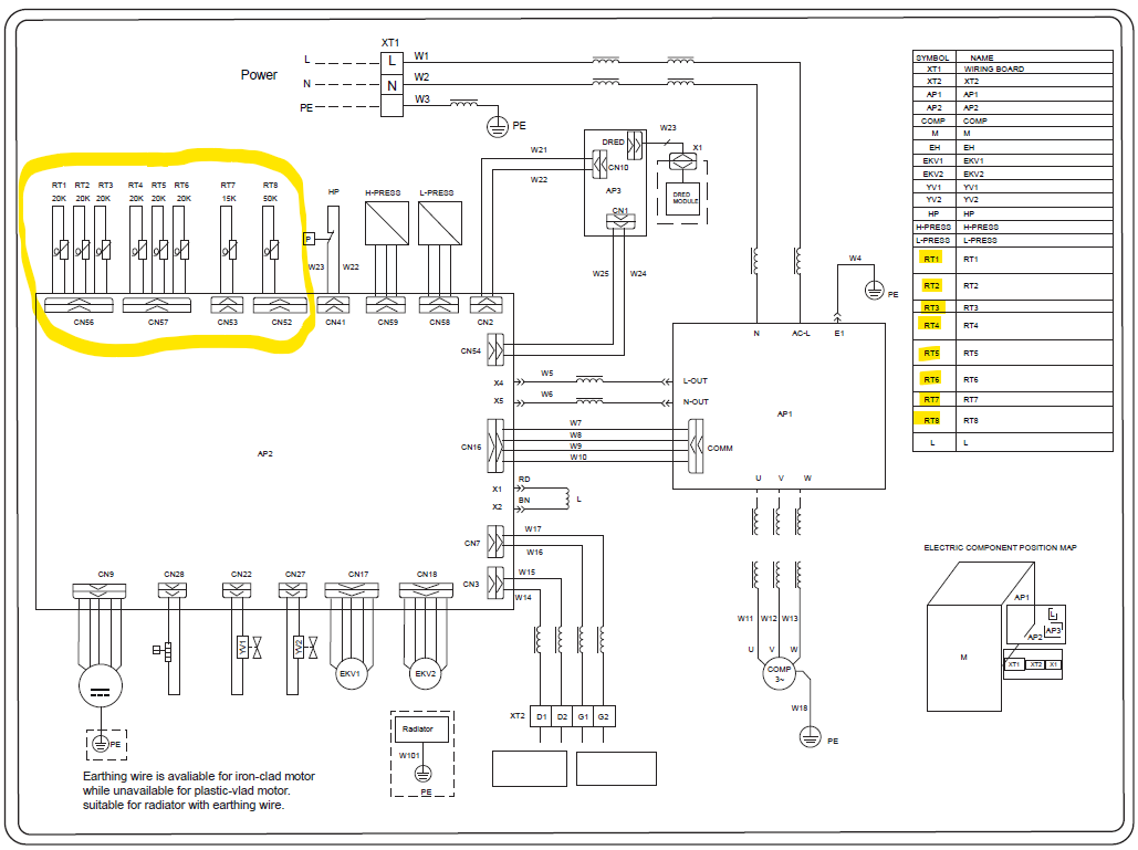
Use the sensor connector locations on the outdoor PCB:
| Connector | Sensor |
|---|---|
| CN56 | RT1, RT2, RT3 |
| CN57 | RT4, RT5, RT6 |
| CN53 | RT7 |
| CN52 | RT8 |
Trace the sensor wiring colours and connector locations to confirm the correct sensor is being tested.
5. Check Sensor Resistance Against Temperature
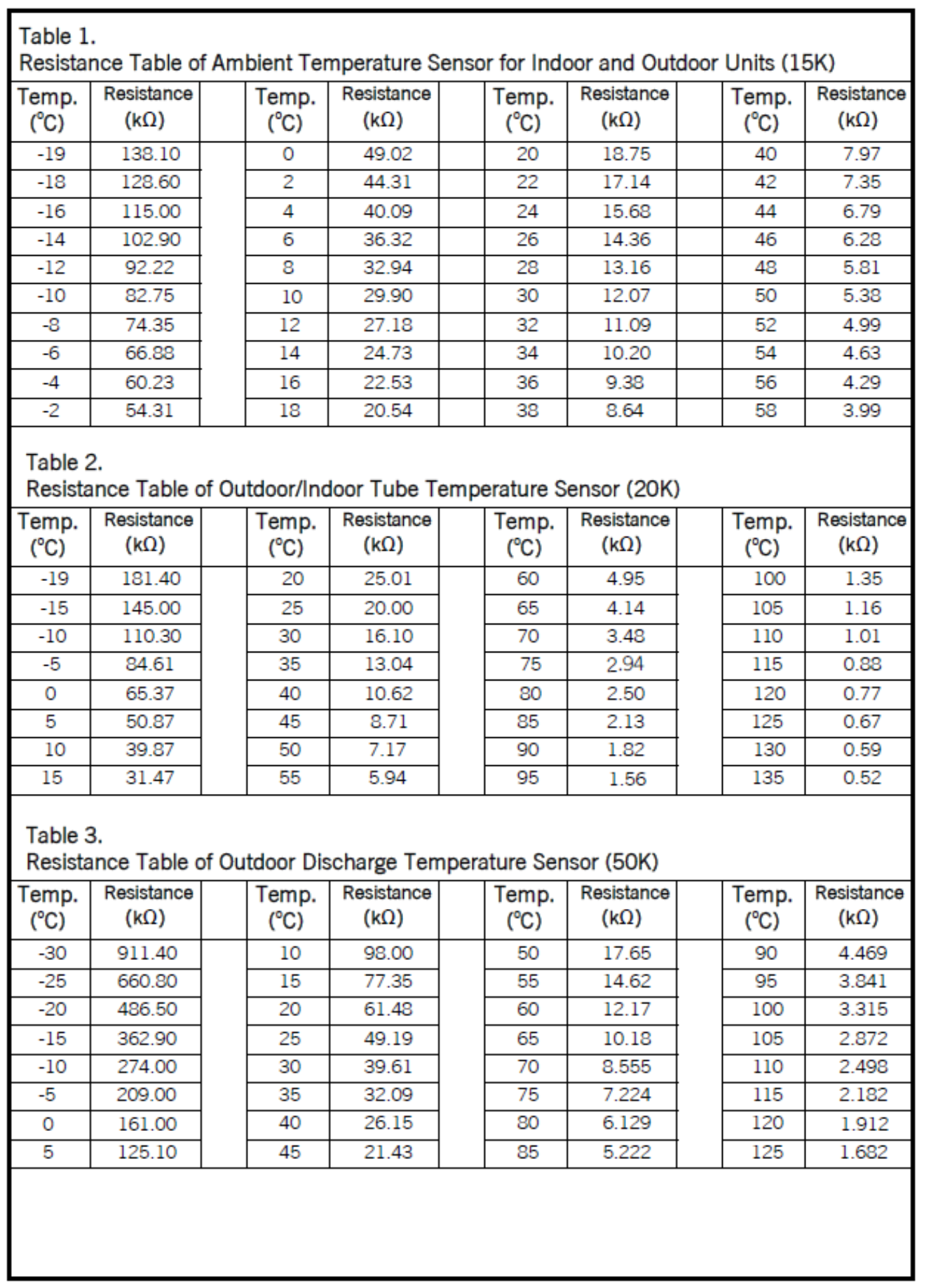
Measure the sensor resistance and compare it to the applicable resistance table in the service manual.
Use:
- Table 1 for RT7 (15 kΩ Outdoor Ambient Sensor)
- Table 2 for RT1–RT6 (20 kΩ Temperature Sensors)
- Table 3 for RT8 (50 kΩ Discharge Temperature Sensor)
If the measured resistance is outside specification for the sensor temperature, replace the sensor.
Sensor Replacement
RT1 to RT6
⚠️ Note: RT1 to RT6 temperature sensors are supplied as a kit of three and are not available individually.
Replace the faulty sensor(s) using the correct replacement kit.
RT7 and RT8
RT7 and RT8 are supplied separately and must be replaced with the correct resistance type:
- RT7 = 15 kΩ
- RT8 = 50 kΩ
Never substitute a different sensor type.
If the Fault Remains
If:
- Sensor resistance is correct
- Wiring is intact
- Connections are secure
but the fault code remains active, the sensor detection circuit on the outdoor main control board may be faulty.
Further diagnosis of the outdoor PCB will be required.
OUTDOOR UNIT - MCMX080D104B, MCMX100D105B
OUTDOOR UNIT - MCMX120D107B, MCMX140D108B, MXMX160D109B
Measure the sensor resistance and compare it to the applicable resistance table in the service manual.
Use:
- Table 1 for RT7 (15 kΩ Outdoor Ambient Sensor)
- Table 2 for RT1–RT6 (20 kΩ Temperature Sensors)
- Table 3 for RT8 (50 kΩ Discharge Temperature Sensor)
If the measured resistance is outside specification for the sensor temperature, replace the sensor.