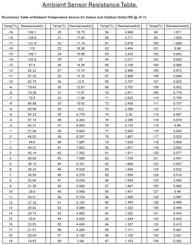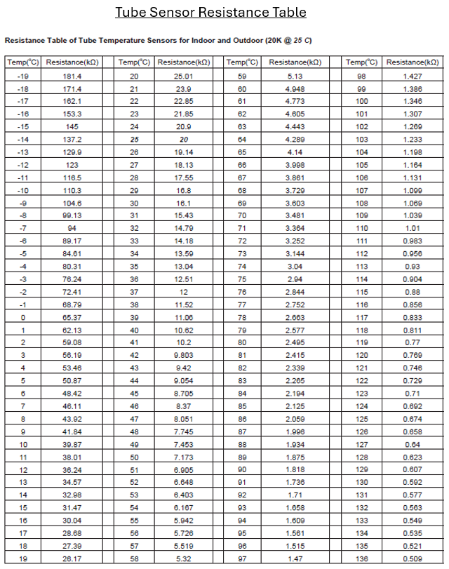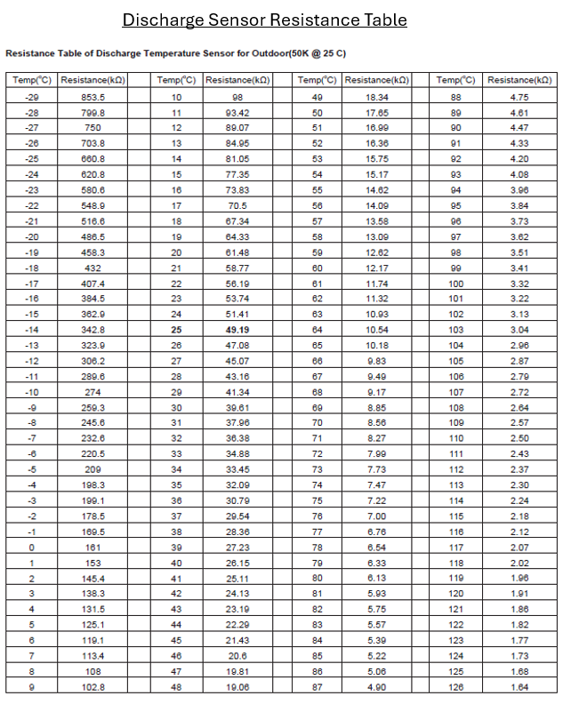
B5 & B7 Temperature sensor malfunction MCHV - sensor diagnostic / resistance measurements and spare part # identification
⚠️ Safety Notice – Reverse Cycle Air Conditioners
This equipment must only be installed, commissioned, serviced and repaired by suitably qualified and licensed personnel.
Before commencing work, complete a task-specific risk assessment and ensure electrical isolation procedures, safe access, adequate service clearances and appropriate PPE have been considered. All work must comply with applicable regulations, standards and manufacturer requirements.
Particular care must be taken when working around electrical systems, refrigerant circuits, moving parts, roof spaces, ceiling spaces, confined spaces and working-at-heights hazards where applicable.
Do not proceed if safe access, required clearances, confined space risks or appropriate safety controls cannot be achieved and maintained.
Safety takes priority over diagnosis, repairs, installation schedules and customer expectations. If the task cannot be completed safely, it must not proceed until the risks have been adequately controlled.
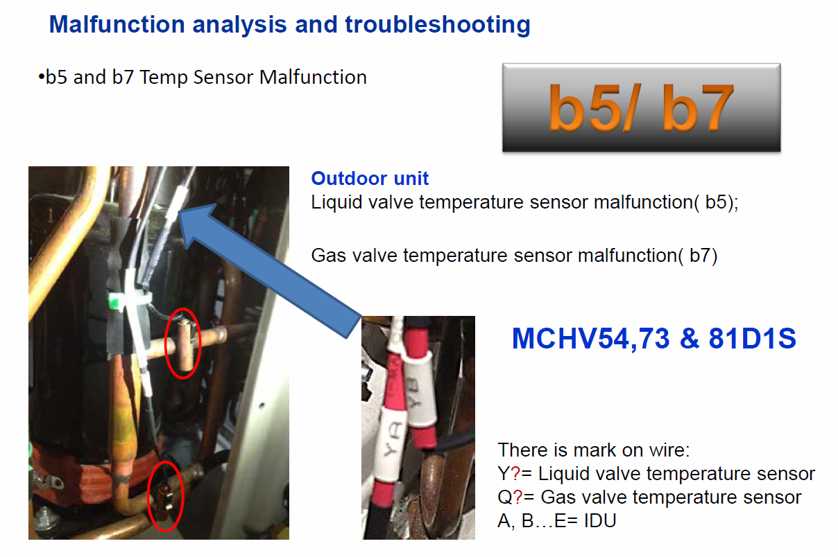
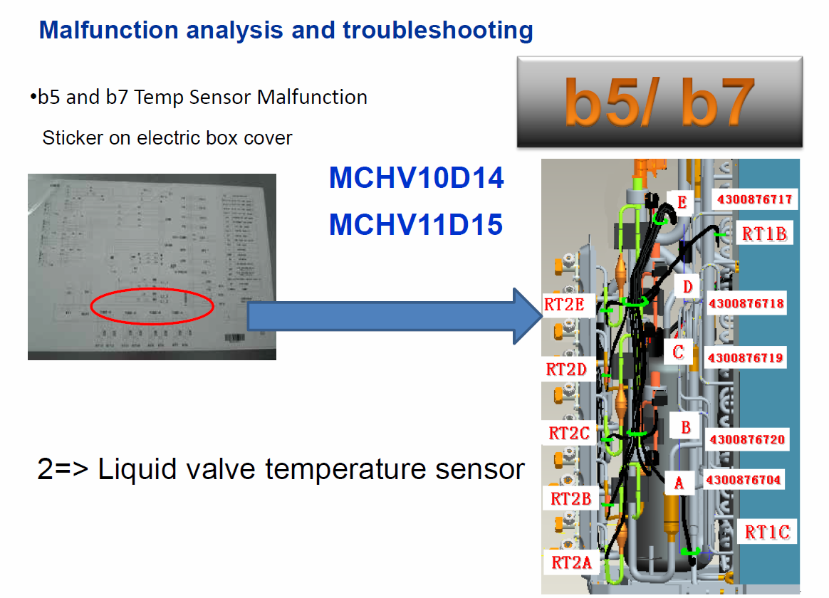
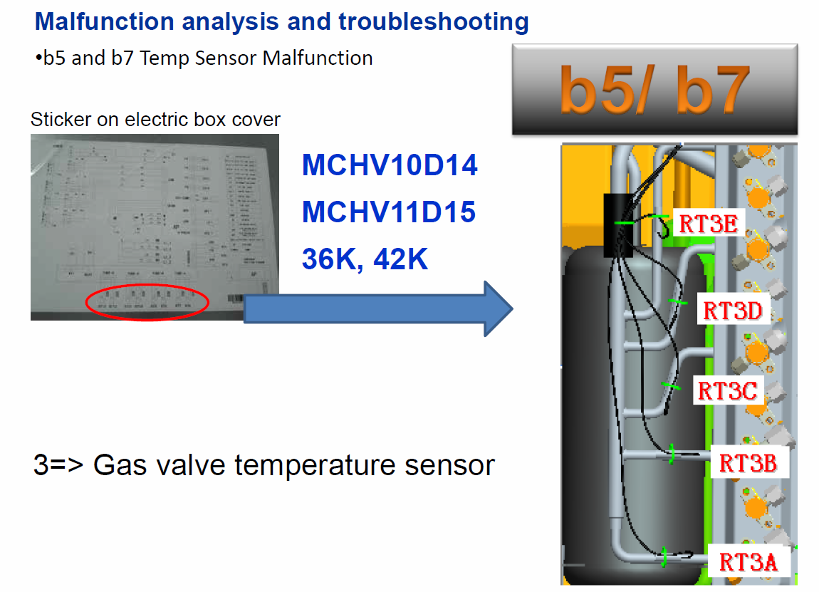
MCHV multi split system - sensor diagnostic / resistance measurements and spare part # identification
Model - MCHV
Multi Split System, Sensor Identification.
There are only 3 types of sensors used in the Braemar Multi systems:

MCHV54D12, MCHV73D13, MCHV81D14
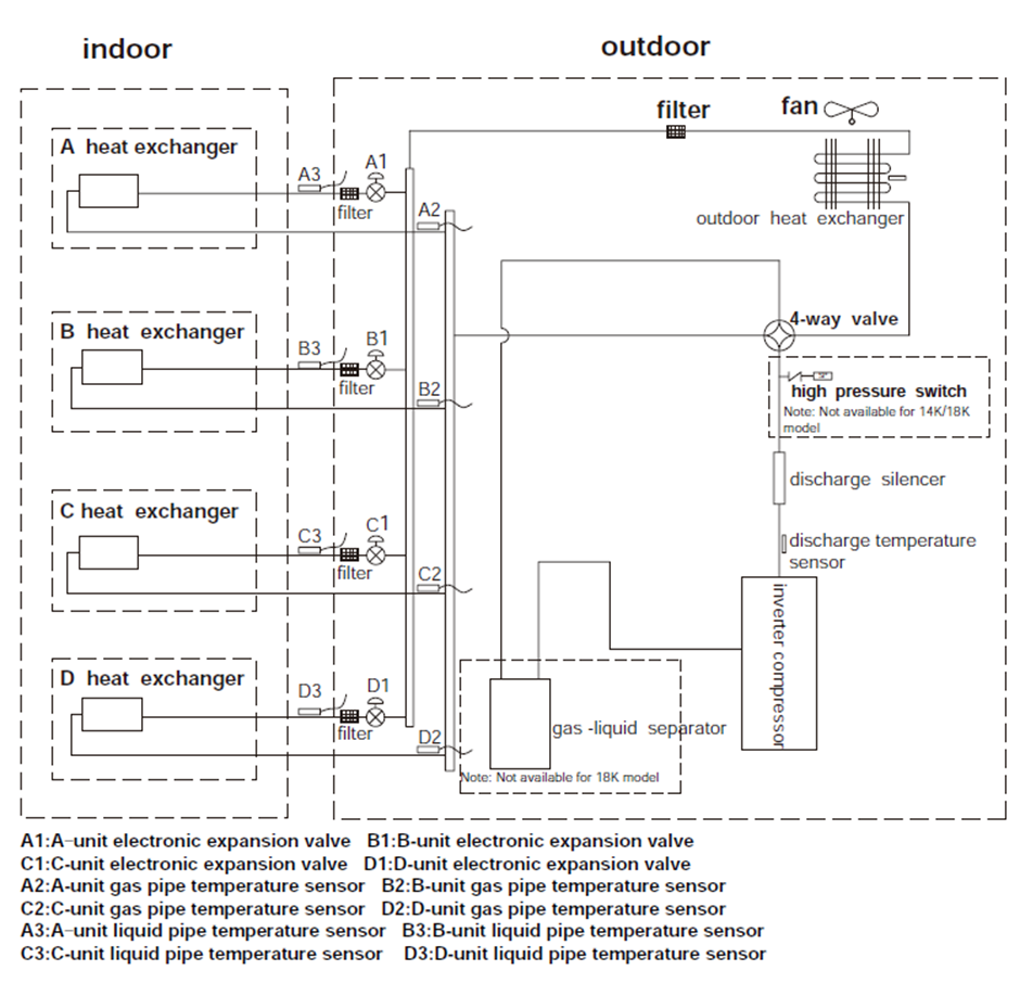
All gas and liquid tube type sensors for each pipe system, are identified by colour and length
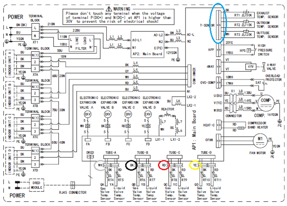
All gas and liquid tube type sensors for each pipe system, are identified by colour and length
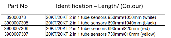
There is also the Main Sensor for the Outdoor unit, which are connected in the same plug.
(Listed on the Outdoor PCB as - T-Sensor.)

MCHV10D14, MCHV11D15
Using the Wiring diagram located on the Outdoor unit electrical box assembly, identify the sensors and complete resistance checks. (See below resistance tables to match)
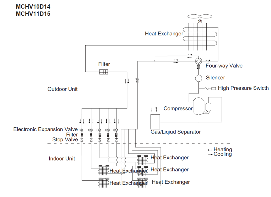
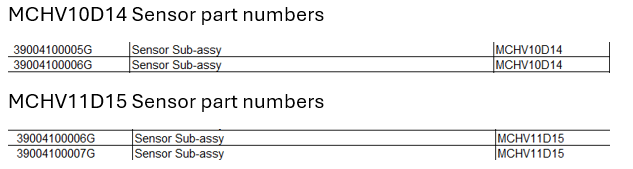
By following these below steps, you can efficiently identify and check the sensors on your outdoor unit.
Locate the Wiring Diagram: Find the wiring diagram on the outdoor unit’s electrical box assembly. This diagram will show you the layout and connections of all components.
Identify the Sensors: Look for symbols or labels on the diagram that indicate sensors. Common sensors might include temperature sensors, pressure sensors, and humidity sensors.
Match with Resistance Tables: Use the provided resistance tables to match each sensor. The tables will give you the expected resistance values for each sensor type.
Perform Resistance Checks:
- Turn off Power: Ensure the unit is powered off to avoid any electrical hazards.
- Disconnect Sensors: Carefully disconnect the sensors from the circuit.
- Measure Resistance: Use a multimeter to measure the resistance of each sensor. Compare the readings with the values in the resistance tables.
- Record Results: Note down the measured values and check if they fall within the expected range.
All sensors can be checked using the Resistance Charts available and cross checking their values, if not found to be open circuit for sensor faults