Pre‑2020 CW‑H – FC7 (Fault Code 7) Motor Error:
Diagnostic Procedure & Resolution Guide
Fault Code 7 on pre‑2020 Climate Wizard CW‑H units indicates the control board has detected a motor fault. For older units using EBM 3‑phase motors, the most common causes are incorrect or unstable 3‑phase supply, followed by issues with the motor fault‑relay signal wiring.
All electrical diagnosis and repairs must be performed by suitably qualified, licensed electricians/technicians in accordance with local regulations and standards. Isolate and lock out electrical power before opening the control box or handling wiring.
This guide provides a structured method to confirm the correct electrical power supply, inspect the motor wiring, and determine whether the fault is in the motor or the site wiring.
1. Confirm Correct 3‑Phase Power Supply
Before inspecting any motor wiring, you must verify that all three phases are present, correctly balanced, and reaching the motor.
1.1 Test at the incoming isolator
Measure:
- Phase to Neutral (L1–N, L2–N, L3–N)
- Phase to Phase (L1–L2, L2–L3, L3–L1)
Expected:
- Phase‑to‑Neutral (L1–N, L2–N, L3–N): ≈220–240 V AC
- Phase‑to‑Phase (L1–L2, L2–L3, L3–L1): 380–415 V AC
- Frequency: 50 Hz
Balance target: As a rule of thumb, aim for ≤ ±6% imbalance across phases (site practice). Any missing phase or significant imbalance will immediately trigger FC7. (Imbalance figure is best‑practice guidance for field diagnosis.
Where to Measure (trace the supply to the motor)
Measure both L–L and L–N at each stage to ensure correct voltage reaches the motor:
- Incoming isolator (supply into the unit)
- Motor contactor (input and output)
- Motor power terminals (motor plug or terminal block, depending on motor generation)
Why this matters: CW-H motors are electrically reliable; incorrect site voltages, loose terminations, or a failing contactor are common root causes of FC7.
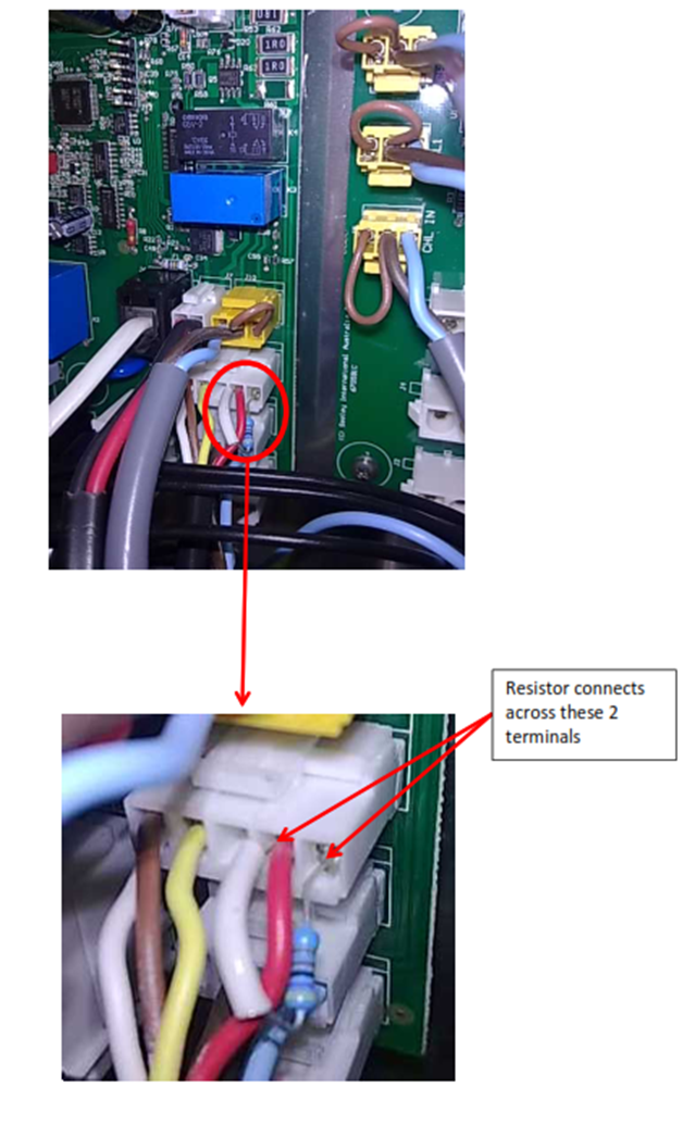
2. Check Motor Pull‑Up Resistor (Motor Fault Circuit)
Pre‑2020 units rely on an external pull‑up resistor for motor fault detection (see diagram below).
Inspect:
- Confirm the resistor is firmly connected into the wiring harness.
- Look for corroded pins, loose crimps, damaged insulation.
- Any open circuit here will register as FC7.
3. Inspect Motor Cable Connection
For GEN 3 EBM Motors (Plug‑in motor cable):
- Ensure the motor plug is fully seated on the motor board.
- Inspect the plug for bent pins or water ingress.
- Verify wiring order and that the lock tab is engaged.
For earlier EBM motors with terminal blocks:
- Physically tighten L1/L2/L3 and earth terminal - Poor contact = immediate motor fault
- Verify correct phase order (L1/L2/L3 using simple rotation check) - Briefly run the fan and confirm it spins in the same direction as the arrow on the fan housing. If it spins the opposite way, swap any two phases at the motor terminal block and re‑test. (Swapping any two phase's reverses rotation; a reversed fan will underperform and may lead to FC7 under load.)
4. Inspect Motor Fault Signal Wiring (Yellow & White Wires)
The motor contains a normally‑closed relay.
When the motor detects an internal issue, the relay opens → PCB detects open circuit → FC7.
Common field failures:
- Broken or corroded yellow/white wires near the motor
- Loose spade terminals in the control box
- Water ingress at the motor end
- Incorrect polarity on reconnection
Symptoms of wiring fault:
- Motor starts briefly and stops
- FC7 immediately after startup
- FC7 only in high speed or load conditions
5. Test the Motor Fault Signal Wiring (Definitive Test)
This is the quickest way to determine wiring vs motor fault. (see diagram below)
Procedure:
- At the PCB, bridge the two motor fault signal terminals (yellow & white).
- Reset power.
- Start the cooler.
Interpretation:
| Result | Meaning | Action |
|---|---|---|
| Motor runs normally with wires bridged | Fault in wiring between motor and control box | Repair/replace yellow & white wiring |
| Motor still shows FC7 even when bridged | Internal motor issue (relay fault inside motor) | Replace motor Always confirm all supply voltages and phase balance as per Step 1 before condemning the motor. |
⚠️ Important Warning
Remove the temporary bridge link immediately after testing.
Leaving it in place will disable fault detection and can hide a real motor fault.
The bridging step and any subsequent corrective work must only be carried out by suitably electrical qualified personnel under an isolated, locked‑out supply.
6. Additional Checks for Pre‑2020 Units
- Inspect motor plug cavity for water ingress
- Dry and clean any moisture/corrosion
- Verify pull‑up resistor is secure
- Confirm correct wiring colours (older harnesses vary)
- Confirm no rodent damage at the motor or control box
If everything checks out and FC7 persists → motor replacement is likely required.
Images below
Make sure the pull-up resistor for the motor circuit is firmly attached to the motor's wiring connector.
At the back of the motor, make sure the motor cable plug is firmly connected to the motor board and wired correctly. Note that only Gen 3 EBM motors use this plug setup; older EBM models use terminal blocks.
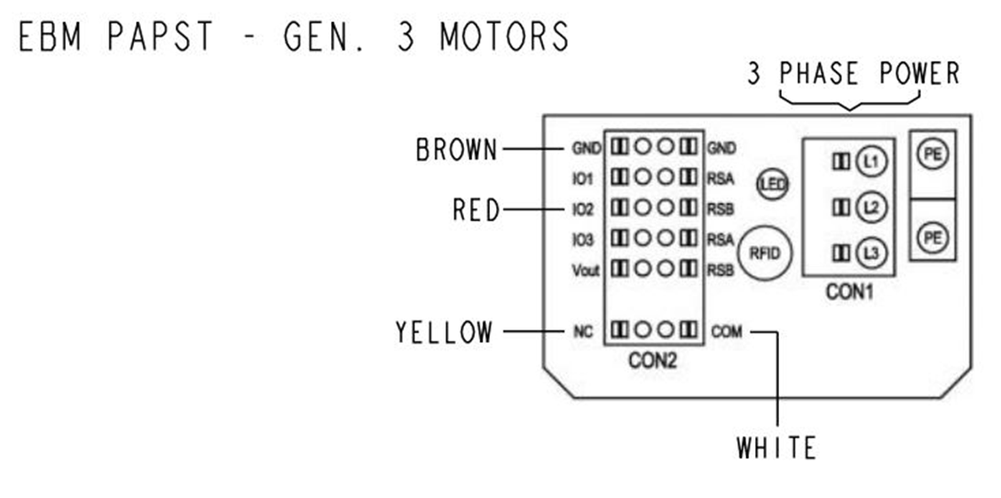
If the motor runs briefly and then stops, the problem is likely with the fault signal wiring (yellow and white). The motor's relay is normally closed, but if the motor detects a fault, it will open this contact and cause an FC7 error.
Possible causes:
- A real fault in the motor
- Poor connection or damaged fault signal wiring (yellow and white) at the motor or control box
To test the wiring:
- Bridge the yellow and white motor wires at the PCB.
- If the motor runs, the fault is with the signal wiring.
- If it doesn't run, the motor itself may have a fault. Always confirm all supply voltages and phase balance as per Step 1 before condemning the motor.
The bridging step and any subsequent corrective work must only be carried out by suitably electrical qualified personnel under an isolated, locked‑out supply.