ACHV / ASHV Austral-air R32 High Wall Split - Service Manual - ASHV-04-A Service Manual - Austral-Air AU 2511
For a comprehensive complete 56-page Service Manual including fault finding flow charts download Pdf attached,


For a comprehensive complete 56-page Service Manual including fault finding flow charts download Pdf attached,


For a comprehensive complete 56-page Service Manual including fault finding flow charts download Pdf attached,
Austral-Air R32 High Wall Split System – Error Code & Troubleshooting Guide
Document Reference
Title: Austral-Air® R32 High Wall Split System – Service Manual
Publisher: Seeley International
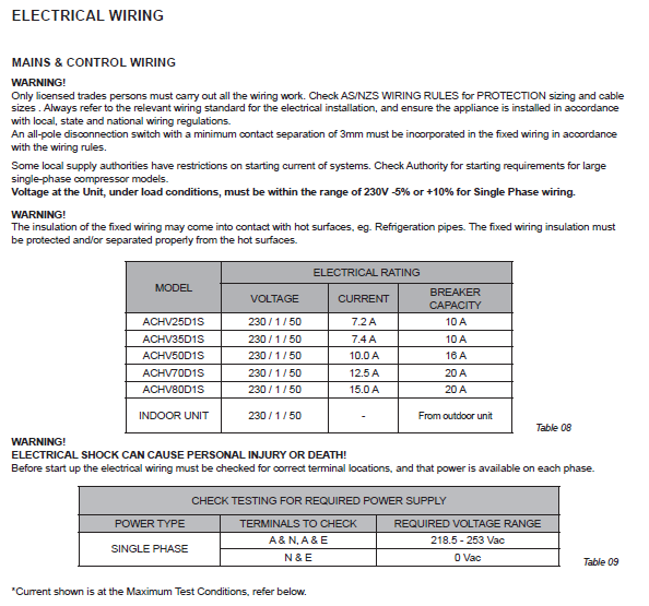
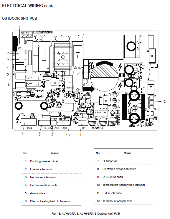
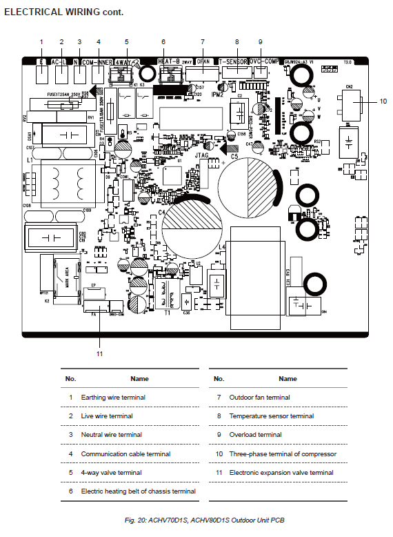
Models Covered: ACHV25D1S / ASHV25D1S through ACHV80D1S / ASHV80D1S
Safety Notice
These systems use R32 flammable refrigerant. All servicing must be performed by qualified, licensed technicians. Refer to the manual’s safety section for handling procedures, ventilation requirements, and electrical isolation protocols.
Error Code Reference Table
| Error Code | Fault Description | Symptoms | Likely Causes | Recommended Actions |
|---|---|---|---|---|
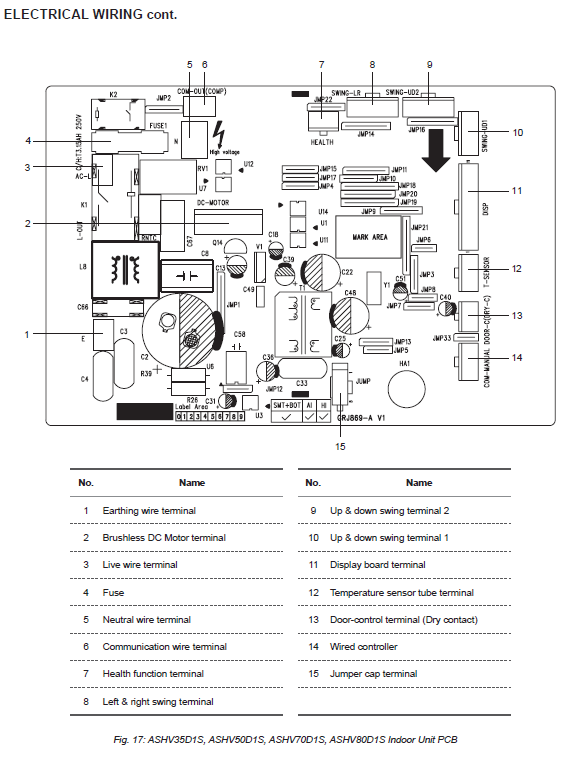
| C5 | Jumper Cap Fault | Unit stops | Missing, loose, or damaged jumper cap | Check jumper cap installation; replace if faulty |
| E6 | Communication Fault | Compressor stops; indoor fan may run | Wiring issues, board faults | Check wiring, replace control boards if needed |
| H5 / P5 | IPM / Over-phase Current Protection | Compressor stops | Incorrect wiring, high refrigerant charge, dirty coils | Check compressor wiring, refrigerant level, clean coils |
| H3 / E4 | Compressor Overload / High Discharge Temp | Compressor stops | Faulty overload protector, refrigerant issues | Test overload protector, check refrigerant charge |
| F1–F5 | Sensor Faults | Compressor stops; indoor fan may run | Loose or damaged sensor, board fault | Check sensor connections, replace sensor or board |
| H6 | Indoor Fan Motor Fault | Fan doesn’t operate | Motor or board fault | Test motor voltage, replace motor or board |
| E5 | AC Overcurrent Protection | Compressor stops | Dirty coils, fan issues, high load | Clean coils, check fan operation, test current draw |
| E8 / L9 / H4 | High Temp / Power / System Abnormal | Compressor stops | High ambient temp, poor ventilation | Improve airflow, check fan and refrigerant |
| H7 | Compressor Desynchronization | Compressor stops | Wiring or refrigerant issues | Check UVW wiring, refrigerant charge |
| Lc | Startup Failure | Compressor fails to start | Unbalanced pressure, wiring, refrigerant | Wait 3 mins, check wiring, refrigerant level |
| pU | Capacitor Charging Fault | Compressor stops | Voltage issues, reactor wiring | Measure voltage, check reactor wiring |
| Other Sensor Faults | Various | Compressor stops | Sensor damage or wiring fault | Replace sensor, check wiring |
Troubleshooting Flowcharts
Each error code is supported by a detailed diagnostic flowchart from the service manual. These flowcharts guide technicians through step-by-step fault isolation and resolution.
Austral-Air R32 Troubleshooting Flowcharts PDF attached
Flowchart Summaries
C5 – Jumper Cap Fault
- Check jumper cap installation on indoor control board.
- Replace jumper cap or control board if issue persists.
E6 – Communication Fault
- Inspect wiring between indoor and outdoor units.
- Test communication circuits; replace faulty boards.
H5 / P5 – IPM & Over-phase Current
- Verify compressor wiring (UVW), voltage, refrigerant charge.
- Clean heat exchangers: replace compressor or board if needed.
H3 / E4 – Compressor Overload / High Temp
- Test overload protector and expansion valve.
- Check refrigerant charge and replace faulty components.
F1–F5 – Sensor Faults
- Inspect sensor connections and resistance.
- Replace sensor or control board.
H6 – Indoor Fan Motor Fault
- Check motor terminals, voltages, and blade movement.
- Replace motor or indoor control board.
E5 – AC Overcurrent
- Check power voltage, fan operation, compressor condition.
- Clean coils and replace control board if unresolved.
E8 / L9 / H4 – High Temp / Power / Abnormal
- Check ambient temperature, fan operation, airflow.
- Replace fan capacitor or control board.
H7 – Compressor Desynchronization
- Check UVW wiring, refrigerant charge, ventilation.
- Replace compressor or control board.
Lc – Startup Failure
- Wait 3 minutes, check wiring and refrigerant charge.
- Replace compressor or control board.
pU – Capacitor Charging Fault
- Measure capacitor voltage and AC input.
- Check reactor wiring; replace control board.
Sensor Resistance Reference
Refer to the Resistance Chart in the manual (page 44) for expected values when testing temperature sensors.
Additional Diagnostic Tools
- Three-pin motor testing procedure (page 50)
- Indoor unit disassembly steps (pages 45–49)
- Wi-Fi connection check (page 52)