
⚠️ Safety Notice – Gas Heating Products
This appliance must only be installed, commissioned, serviced and repaired by suitably qualified and licensed personnel.
Before commencing work, complete a task-specific risk assessment and ensure gas and electrical safety requirements, ventilation provisions, safe access, adequate service clearances and appropriate PPE have been considered. All work must comply with applicable regulations, standards and manufacturer requirements.
Particular care must be taken when working around gas systems, electrical components, combustion products, hot surfaces, moving parts, roof spaces, ceiling spaces and confined spaces.
Do not proceed if safe access, required clearances, ventilation requirements, confined space risks or appropriate safety controls cannot be achieved and maintained.
Safety takes priority over diagnosis, repairs, installation schedules and customer expectations. If the task cannot be completed safely, it must not proceed until the risks have been adequately controlled.
Overview
Applicable Models
- TH3
- TH4
- TH5
- TG Series (with Spectrolink SCC)
Quick Reference
| Model | Zoning Capability |
|---|---|
| TH3 | No zoning |
| TH4 | Up to 4 zones |
| TH5 | Up to 4 zones |
Cooling Operation
| Cooling Type | Zone Operation |
|---|---|
| Evaporative Cooling | Zones inactive |
| Refrigerated Cooling | Zones active |
Before You Start
Ensure you have access to:
- Installation & Service Manual
- Zoning Supplement Manual
- Technical Bulletin A06/08
- Home Owner's Manual
AS5601 requirements take precedence over all installation instructions.
SCC Compatibility
The Spectrolink Comfort Control (SCC) is compatible with:
- Braemar TH & TG Series heaters
- Braemar SPI systems (TA, TE)
- Braemar MPI systems (TM, TE)
- Breezair, Braemar and Coolair evaporative coolers using CPMD electronics
- Refrigerated cooling systems
SCC Initial Setup
Important
The heater and cooler type must be configured within the first 15 minutes of powering the SCC.
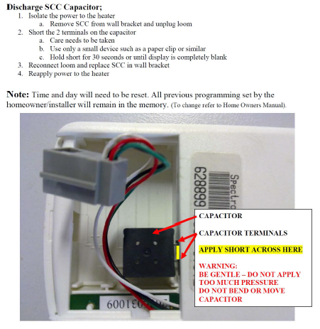
If the SCC has been powered for more than 15 minutes:
- Remove the SCC from the wall plate.
- Disconnect the loom plug.
- Short the terminals on the black capacitor for approximately 30 seconds.
- Continue until the display is completely blank.
- Reconnect and power up.
Time and day will need to be reset. User settings are retained.
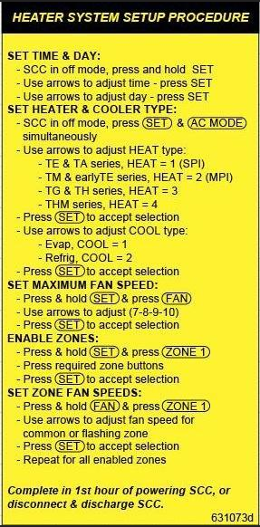
Set Heater and Cooler Type
With the SCC in HEAT mode and OFF:
- Press SET + AC MODE together.
- Select the heater type:
| Heater | Setting |
|---|---|
| TA / TE (SPI) | HEAT 1 |
| TM / TE (MPI) | HEAT 2 |
| TH / TG Series | HEAT 3 |
- Press SET.
- Select the cooler type:
| Cooling Type | Setting |
|---|---|
| Evaporative Cooling | COOL 1 |
| Refrigerated Cooling | COOL 2 |
- Press SET to save.
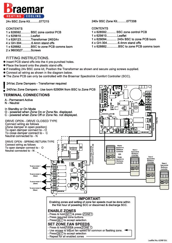
Single SCC Zoning Setup
Enable Zones
- Select HEAT Mode.
- Turn SCC OFF.
- Press SET + ZONE 1.
- Select the required number of zones.
- Press SET.
Set Maximum Fan Speed
- HEAT Mode.
- SCC OFF.
- Press SET + FAN.
- Select fan speed 7–10.
- Press SET.
Set Individual Zone Fan Speeds
- HEAT Mode.
- SCC OFF.
- Press FAN + ZONE 1.
- Adjust the fan speed for each zone.
- Press SET after each adjustment.
Manual Zone Control
Open the SCC door:
- Press a zone button to turn that zone OFF.
- Press again to turn the zone ON.
Multi-SCC Zoning Setup
Requirements
- One SCC per zone.
- SCC must be physically located in the zone it controls.
Commissioning
- Configure maximum fan speed from the Zone 1 (Master) SCC.
- Press SET + ZONE 1 to confirm all SCCs are communicating.
- Set fan speeds for each zone as required.
Each zone can operate independently using its own temperature setting.
Thermostat Location Guidelines
Install the SCC:
✅ Approximately 1.5m above floor level
✅ Within the zone being controlled
Avoid:
- Direct sunlight
- External walls
- Drafts
- Heat-producing appliances
- Supply air outlets
Outlet Airflow Guidelines
In-Ceiling Systems
| Outlet Size | Recommended Airflow |
|---|---|
| 150mm | 55–70 L/s |
| 200mm | 85–100 L/s |
Underfloor Systems
| Outlet Size | Recommended Airflow |
|---|---|
| 150mm | 40–50 L/s |
| 200mm | 60–70 L/s |
⚠️ Excessive airflow can result in increased noise and customer complaints.
⚠️ 200mm outlets are generally not recommended on heating-only systems.
Refrigerated Cooling Systems
For refrigerated cooling installations:
- Select COOL 2 during commissioning.
- Maximum fan speed is fixed at 10.
- Heating zone configuration is used for cooling operation.
Video Guide
For a visual walkthrough of SCC commissioning and setup, view:
Watch Spectrolink SCC Setup Video
Quick Setup Summary (Technician Cheat Sheet)
Within first 15 minutes of power-up:
- Set Time & Day
- SET + AC MODE
- Select:
- HEAT 1 = SPI
- HEAT 2 = MPI
- HEAT 3 = TH/TG
- Select:
- COOL 1 = Evaporative
- COOL 2 = Refrigerated
- SET + FAN → Max Fan Speed
- SET + ZONE 1 → Enable Zones
- FAN + ZONE 1 → Zone Fan Speeds
If setup mode is unavailable, discharge the SCC capacitor and recommission the control.
To view the YouTube video on setting up the Spectrolink SCC system, please follow this link.
To view the YouTube video on setting up the Spectrolink SCC system, please follow this link.