With Troubleshooting Guide & Page References from 859749-L - CW-H Multi-Magic - Install and Operation Manual English
1. Overview
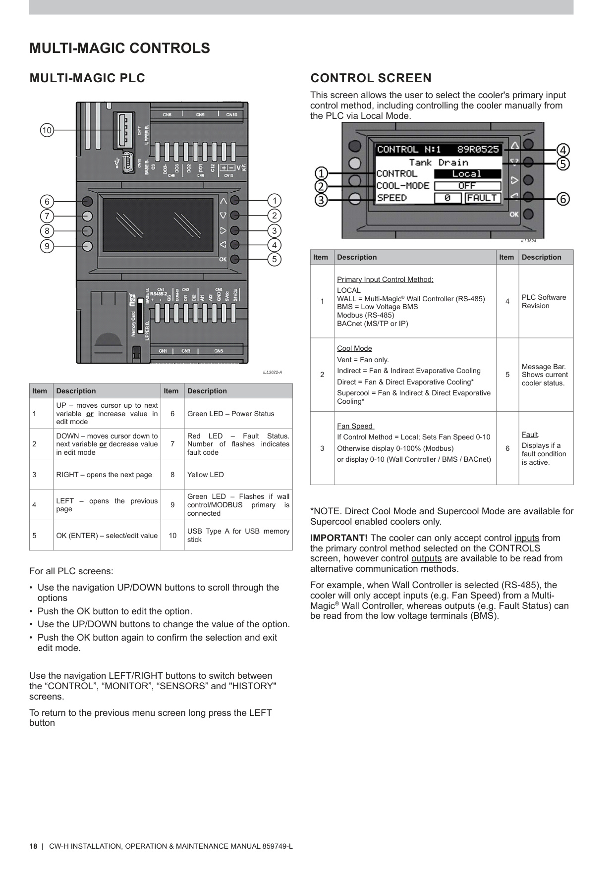
The Multi‑Magic PLC controls the cooler’s fan, pumps, salinity system, communication protocols, sensors, and overall operating logic (PLC overview – p.18).
A PLC replacement may be required when:
- The controller is unresponsive
- Repeated communication faults occur
- Fault Code 1 (PLC–PCBA communication failure) persists
- Physical damage to the display or interface
- Configuration corruption
2. Safety Requirements
Before beginning any PLC service:
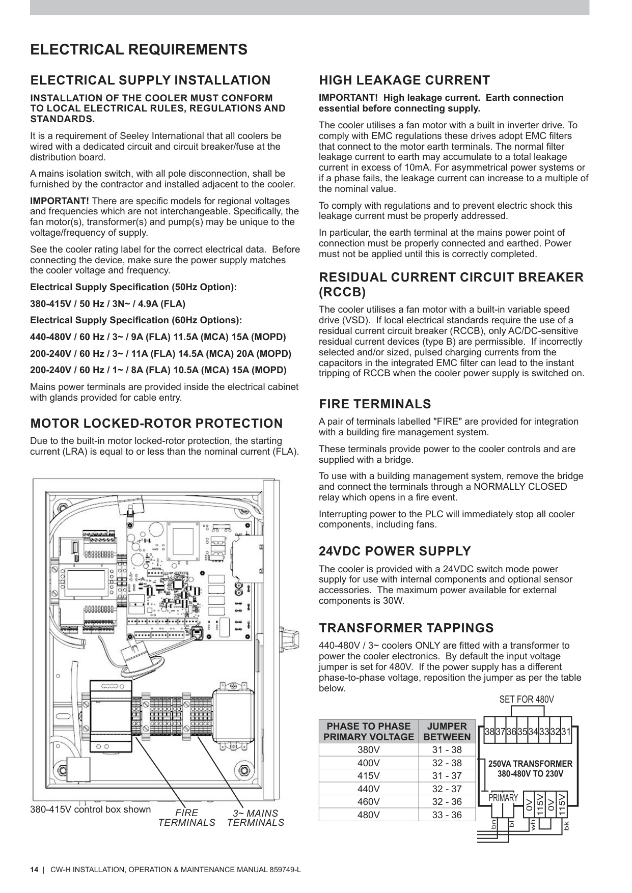
- Isolate power at the mains isolation switch (Electrical Safety – p.14).
- Use lockout/tagout where required.
- Ensure water supply is isolated if working near pumps or wet components.
3. Tools & Equipment Required
- Phillips head screwdriver
- Flat blade screwdriver
- Anti‑static wrist strap
- Replacement Multi‑Magic PLC (correct model & voltage)
4. Accessing the PLC
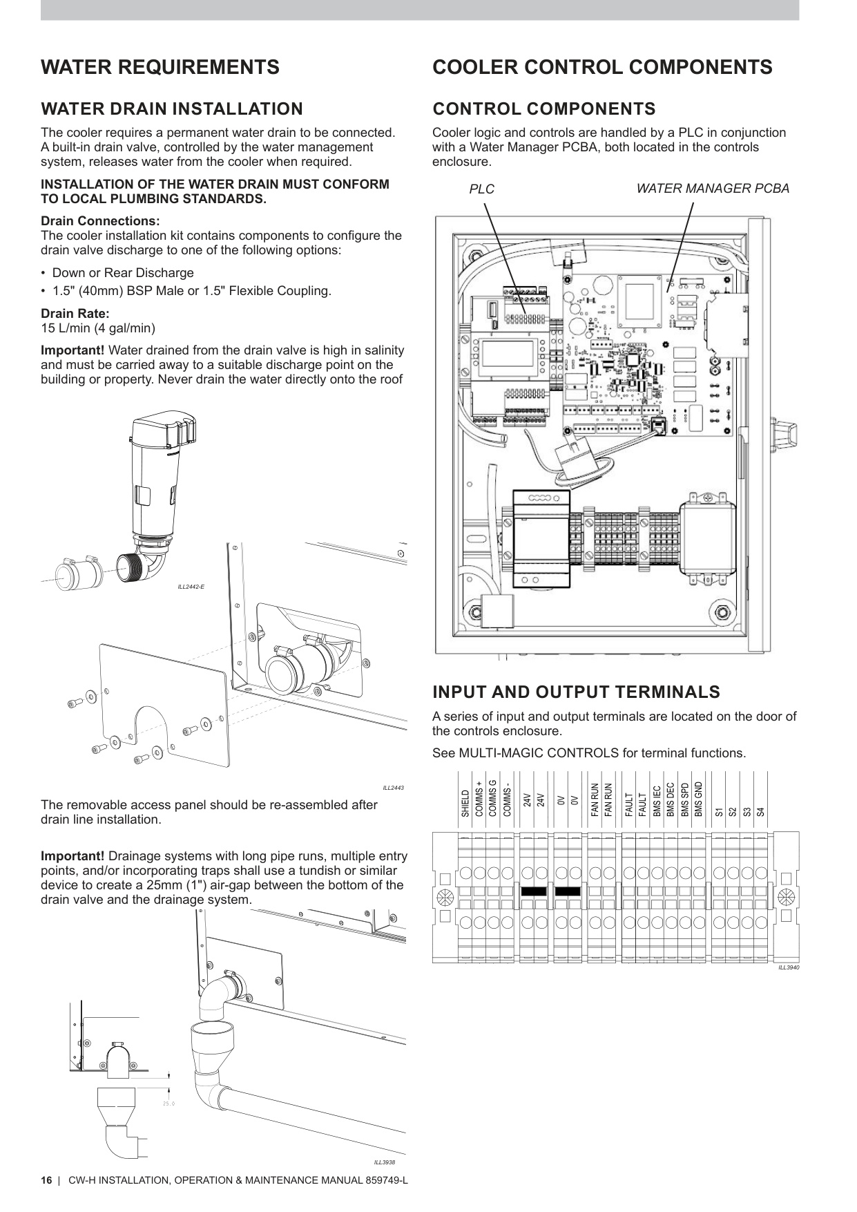
- Open the electrical enclosure door (see Cooler Control Components – p.16).
- The PLC is mounted on the enclosure door and includes the LCD screen, navigation keys, USB port, and indicator LEDs (PLC layout – p.18).
5. Removing the Existing PLC
- Isolate power before disconnecting anything.
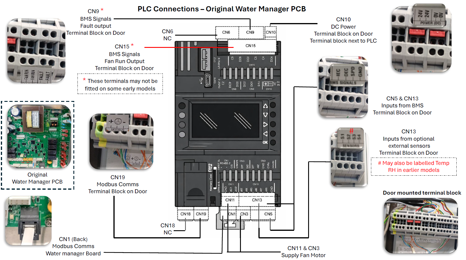
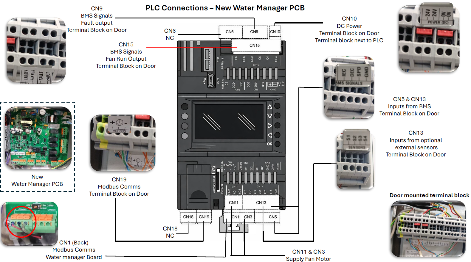
- Disconnect all connectors from the PLC:
- RS‑485 (Wall / Modbus / BACnet)
- Sensor inputs (S1–S4)
- 24VDC power
- BMS inputs/outputs
- Label the connectors for reinstallation (careful labelling and identifying connectors at this stage is important).
- Remove retaining screws and lift out the PLC carefully.
6. Installing the Replacement PLC
- Fit the new PLC and secure using the mounting screws.
- Reconnect wiring as labelled:
- 24VDC supply
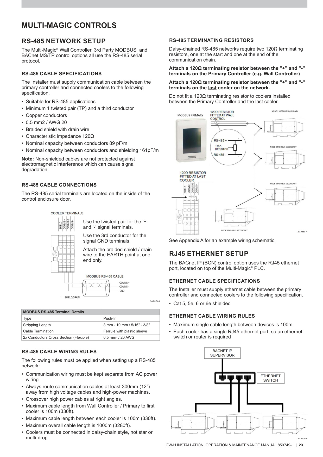
- RS‑485 (observe polarity; see RS‑485 Cable Connections – p.23)
- Sensors (S1–S4) (Sensor inputs – p.19)
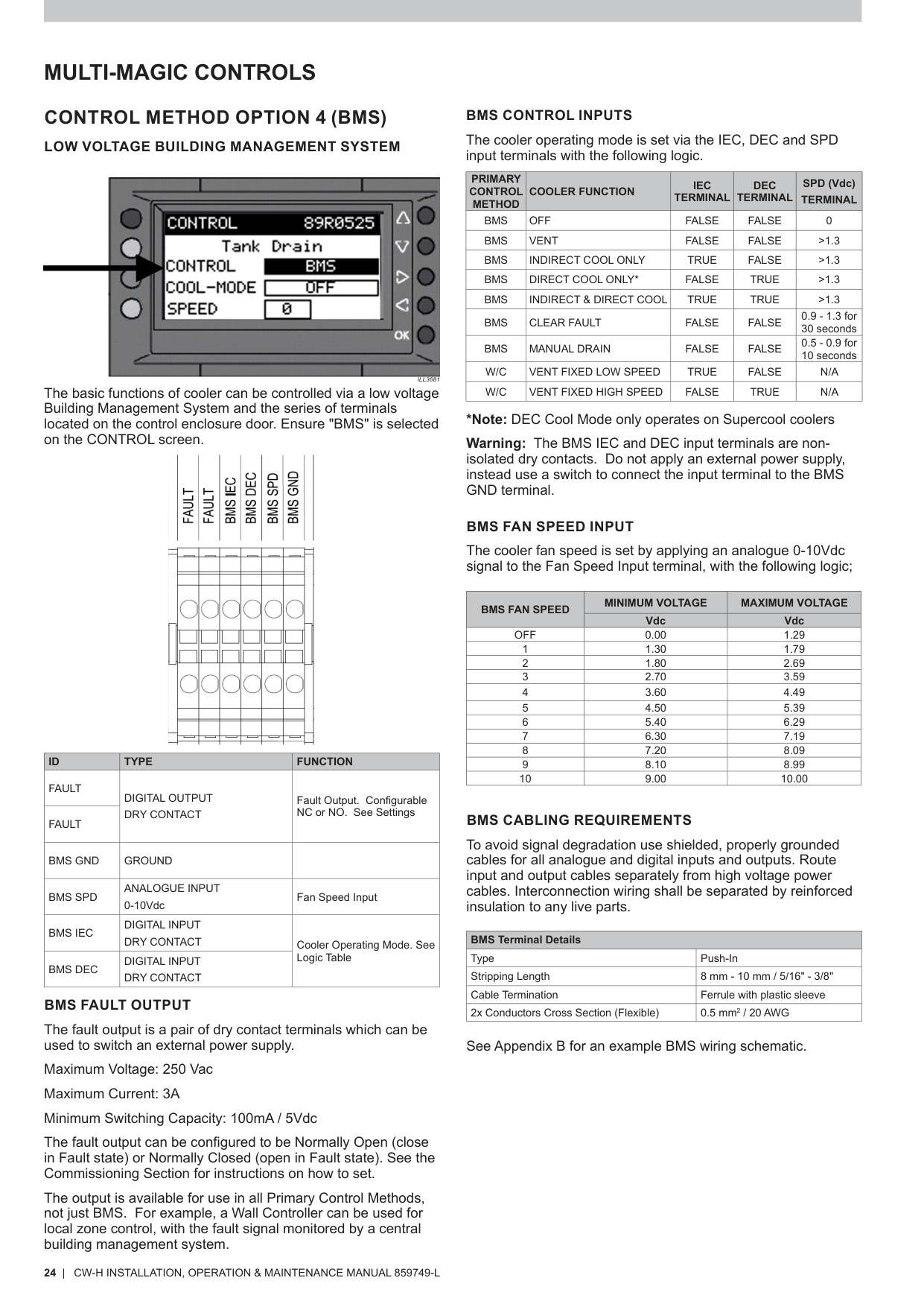
- BMS terminals (BMS Input Logic – p.24)
- Ensure the shielded RS‑485 drain is grounded only at one end (RS‑485 Shielding Rules – p.23).
7. Restoring Configuration After PLC Replacement
7.1 Accessing Setup Menu
- Hold RIGHT button → password screen.
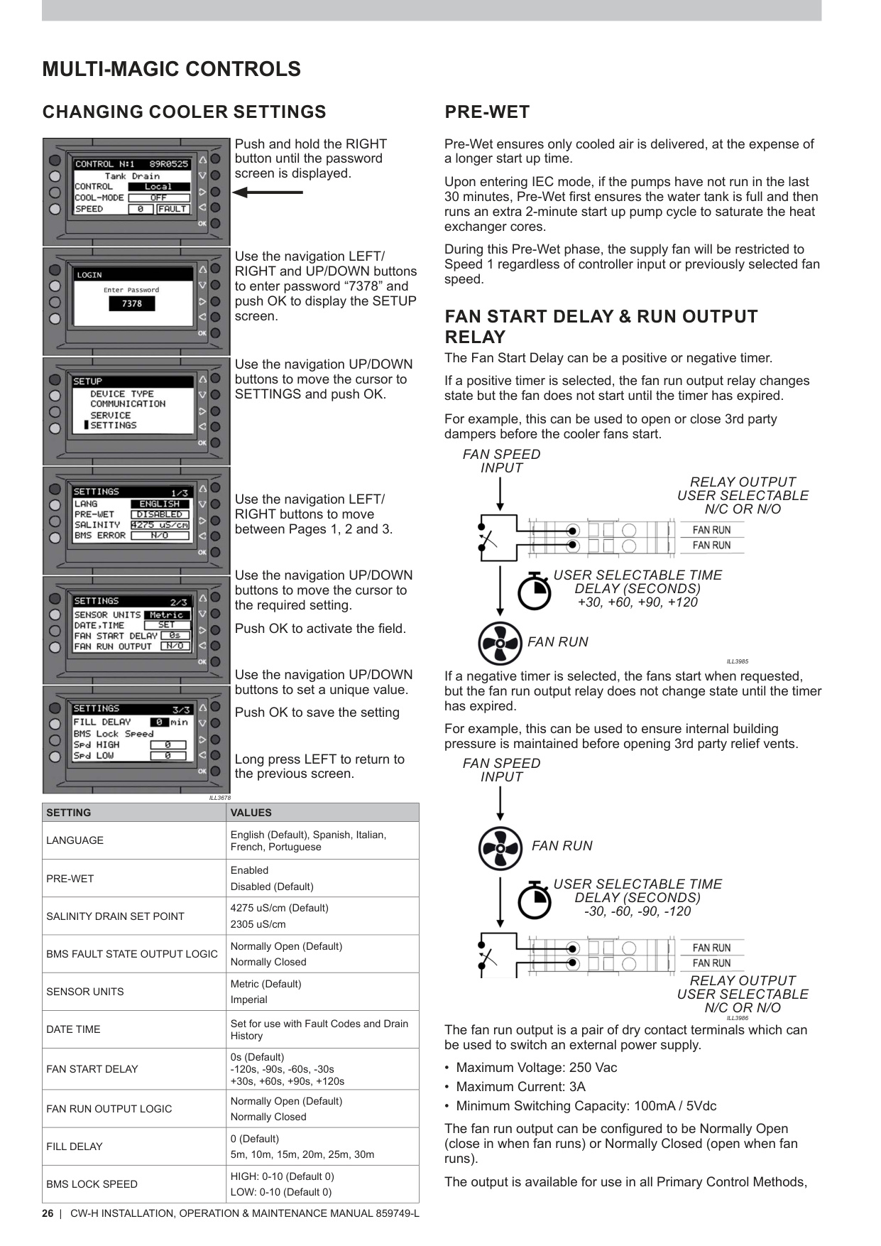
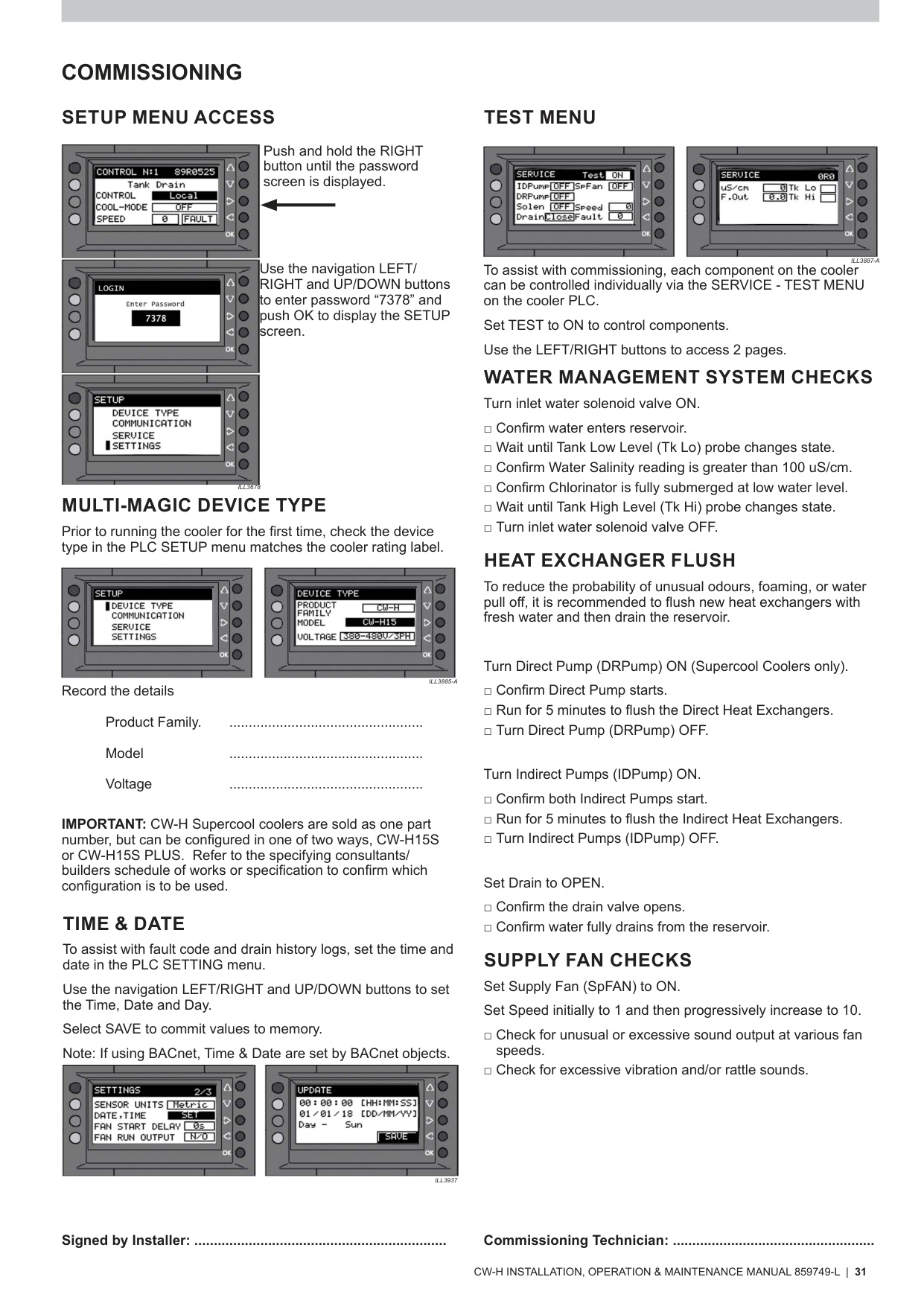
- Enter 7378.
(Setup Access – p.26)
7.2 Select Correct Device Type
Navigate SETUP → DEVICE TYPE (see p.13 & p.31):
- CW‑H15
- CW‑H15S
- CW‑H15S Plus
- CW‑H10
Important: Must match the unit rating label.
7.3 Restore Control Method
Set the correct Primary Input Control Method under CONTROL screen – p.18:
- Local
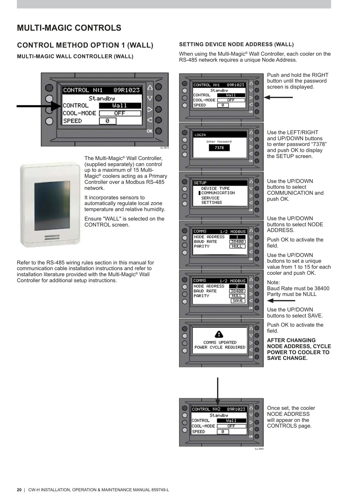
- Wall Controller (RS‑485) (Wall Controller Setup – p.20)
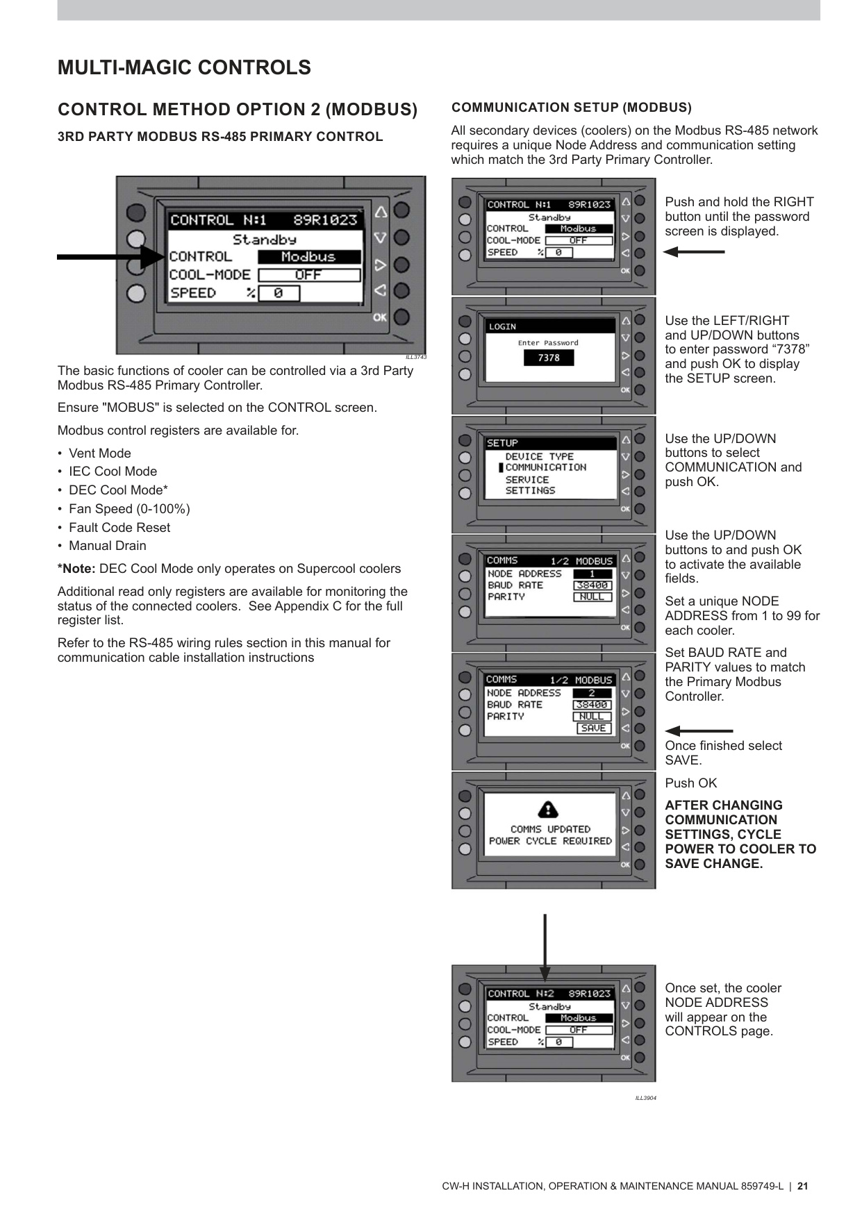
- Modbus (p.21)
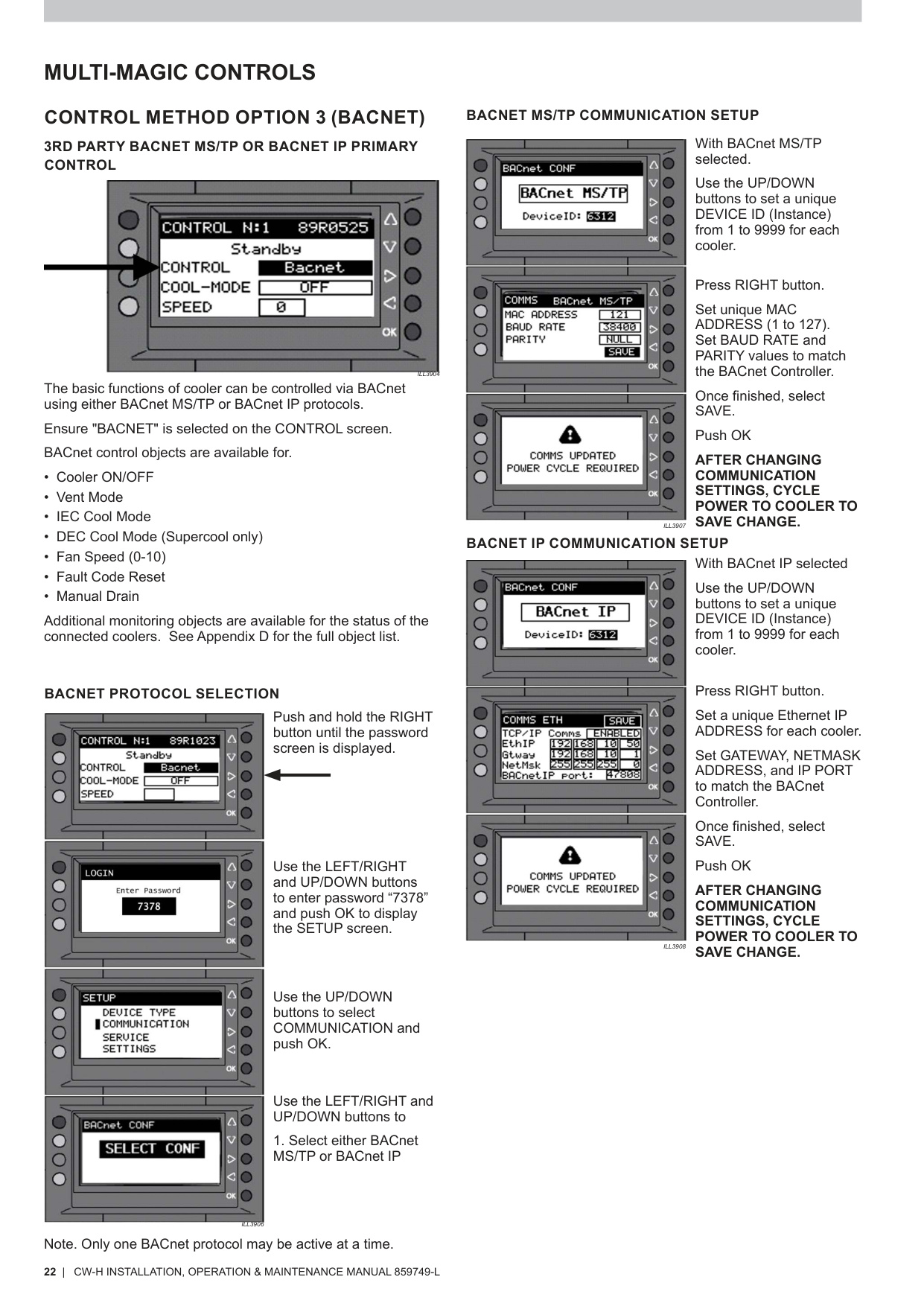
- BACnet MS/TP or IP (p.22)
- BMS Low‑Voltage Control (p.24)
7.4 Communication Settings
Wall Controller (p.20)
- Node: 1–15
- Baud Rate: 38400
- Parity: NULL
- Power‑cycle cooler after saving.
Modbus (p.21)
- Node: 1–99
- Baud/Parity must match supervisor.
BACnet (p.22)
- MS/TP: Device ID (1–9999), MAC, Baud, Parity
- IP: IP Address, Gateway, Subnet Mask, Port (47808 default)
- Power‑cycle after changes.
7.5 Cooler Settings
Under SETUP → SETTINGS (p.26) restore:
- Pre‑Wet
- Salinity Drain Set Point
- Fan Start Delay
- Fill Delay
- BMS Lock Speed
- Sensor Units (Metric/Imperial)
- Date & Time (important for fault & drain history – p.31)
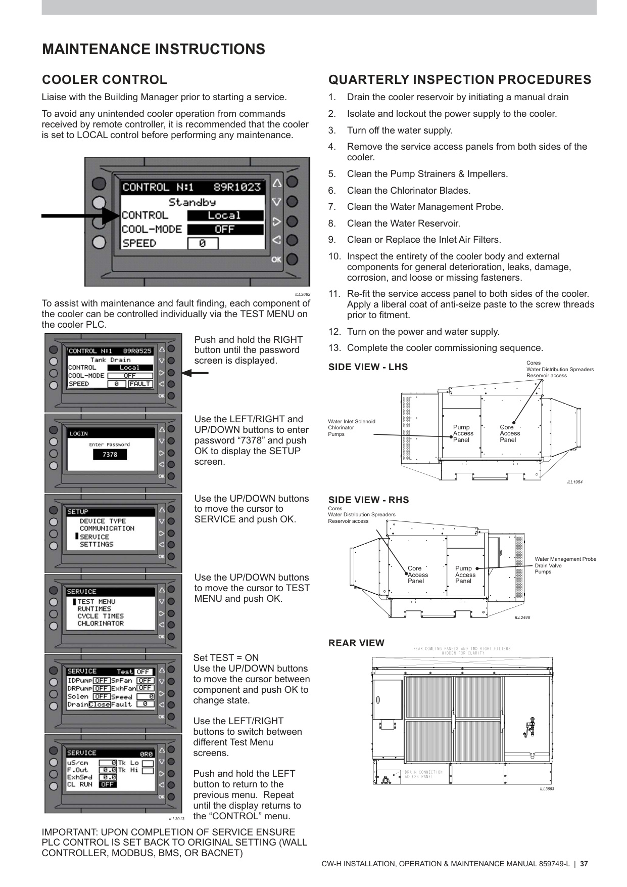
8. Commissioning After PLC Replacement
8.1 Component Testing (Service → Test Menu)
Use the SERVICE → TEST MENU on the PLC (see p.31 & p.37):
- Inlet Solenoid
- Drain Valve
- Indirect Pump
- Direct Pump (Supercool only)
- Fan (Speeds 1–10)
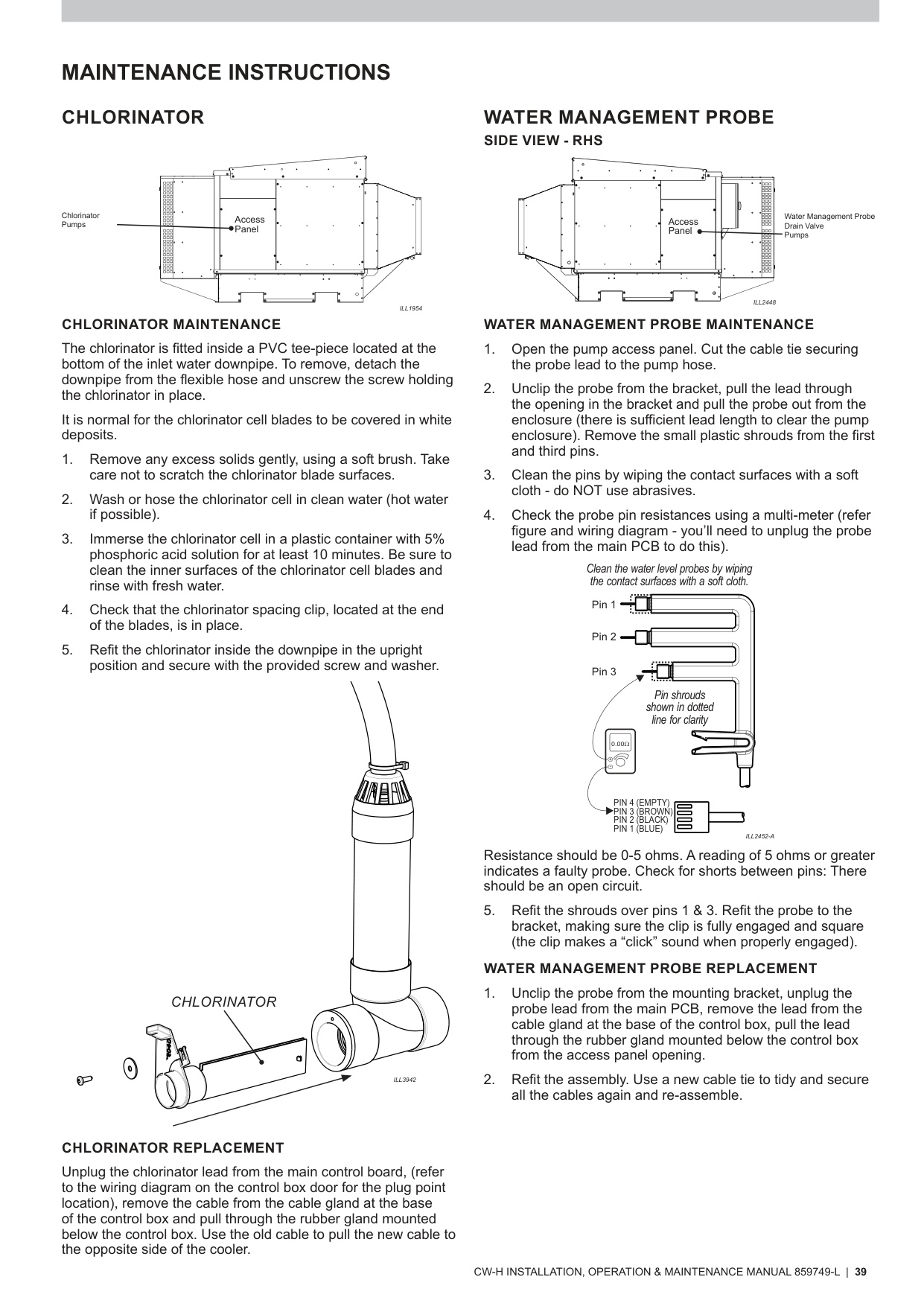
8.2 Water Management System Verification
Checklist from p.31:
- Tank fills until Low Probe → detected
- Tank fills until High Probe → detected
- Salinity reading present (>100 µS/cm)
- Pumps activate in correct sequence
If probes misread, see Probe Maintenance – p.39.
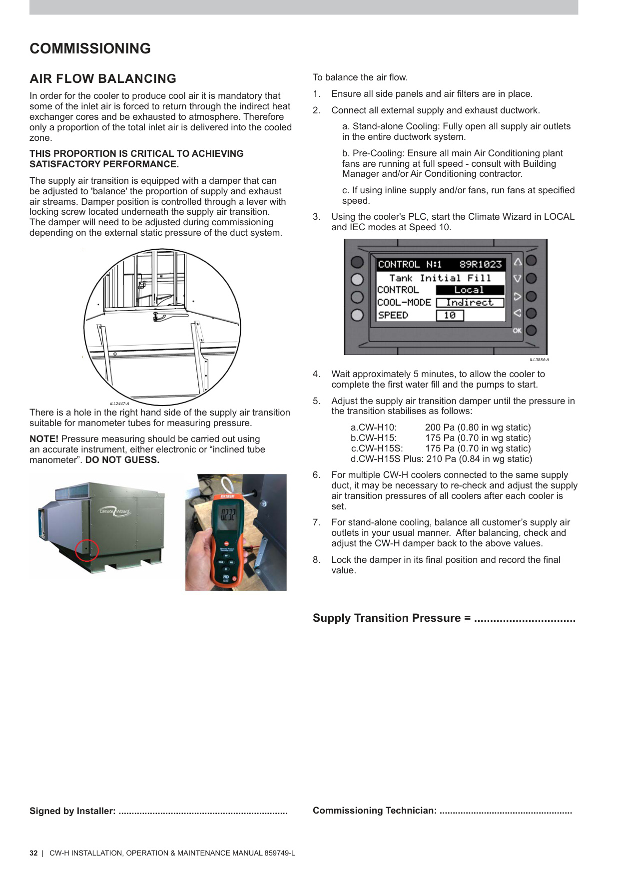
8.3 Airflow / Pressure Balancing
Refer to Air Flow Balancing – p.32:
- Run cooler in LOCAL → IEC, Speed 10 for 5 minutes
- Measure pressure at the transition test port
- Adjust transition damper to target plenum pressure:
- CW-H10: 200 Pa
- CW-H15: 175 Pa
- CW‑H15S: 175 Pa
- CW‑H15S Plus: 210 Pa
9. Troubleshooting – PLC Replacement Issues
9.1 PLC Not Powering On
Possible Causes
- No mains supply to enclosure
- Faulty 24VDC supply (p.14)
Actions
- Check isolation switch
- Verify 24VDC at PLC input
9.2 Wall Controller Not Communicating
Relevant Pages: p.20 (Wall), p.23 (RS‑485 rules), p.29 (Fault Code 16)
Possible Causes
- Incorrect primary control method
- Missing Modbus terminator
- RS‑485 polarity reversed
- Incorrect node address
Actions
- Set CONTROL → WALL
- Check 120Ω terminator at first & last device (p.23)
- Verify A/B wiring
- Confirm node 1–15
9.3 Fault Code 1 – PLC ↔ PCBA Communication Failure
Reference: p.29
Likely Causes
- Loose PCBA harness
- PCBA failure
- PLC failure
Fix
- Check PCBA status LEDs
- Reseat connectors
- Replace PCBA if PLC is new
9.4 Fault Code 7 – Supply Motor Error
Reference: p.29
Causes
- Loose motor cable
- VSD motor error
- Motor fault
Fix
- Check motor power & comms
- Check motor status via MONITOR screen – p.19
9.5 Inadequate Cooling
Reference: Troubleshooting – p.43
Causes
- Running in VENT mode
- DEC not enabled (Supercool)
- Low plenum pressure
- Dirty filters/cores
Fix
- Enable IEC or DEC
- Confirm DEVICE TYPE
- Rebalance airflow (p.32)
- Clean filters (p.40)
9.6 Water System Issues
Causes
- Blocked solenoid strainer (p.38)
- Blocked drain
- Faulty probe (p.39)
Fix
- Clean solenoid mesh
- Clean drain
- Verify probe resistance (<5 Ω)
Quick Page Reference Table
| Topic / Component | Description | Page(s) |
|---|---|---|
| PLC Overview & Button Functions | PLC interface, LEDs, navigation buttons | p.18 |
| Control Screen Functions | Control method selection, fan control, system status | p.18 |
| Monitor Screens | Live status of pumps, valves, fan, water level | p.19 |
| Sensor Screens | S1–S4 sensor configuration | p.19 |
| History Screens | Fault history & drain logs | p.19 |
| Wall Controller Setup | RS‑485 node, baud rate, parity, setup instructions | p.20 |
| Modbus Setup | Node ID, baud/parity settings, communication requirements | p.21 |
| BACnet MS/TP Setup | Device ID, MAC, baud, parity | p.22 |
| BACnet IP Setup | IP address, gateway, subnet mask, port | p.22 |
| RS‑485 Cable Specs | Cable requirements | p.23 |
| RS‑485 Connections | A/B polarity, GND, shield termination | p.23 |
| RS‑485 Wiring Rules | Shielding, daisy‑chain rules, EM separation | p.23 |
| RS‑485 Terminators | Where to install 120 Ω termination | p.23 |
| BMS Input Logic | IEC / DEC / SPD control truth‑table | p.24 |
| BMS Terminals | Fan speed, IEC/DEC contacts, BMS GND | p.24 |
| Manual Drain Function | Behaviour and restrictions | p.25 |
| Freeze Protection | Auto‑drain behaviour below 5 °C | p.25 |
| PLC Settings Menu | Pre‑Wet, delays, BMS lock speed, units, fan relay | p.26 |
| Fault Codes (Descriptions) | Complete fault table including Codes 1, 7, 16 | p.29 |
| Setup Menu Access | Password 7378, navigation | p.31 |
| Device Type Configuration | CW‑H10, H15, H15S, H15S Plus selection | p.31 |
| Test Menu (Service Mode) | Component testing (valves, pumps, fan) | p.31 & p.37 |
| Water Management Checks | Probe detection, salinity update, drain behaviour | p.31 |
| Air Flow Balancing | Plenum pressure targets (all models) | p.32 |
| Pump Maintenance | Strainers, impellers, pump housing | p.38 |
| Water Management Probe Maintenance | Cleaning, resistance testing, troubleshooting | p.39 |
| Drain Valve Maintenance | O‑rings, replacement, sealing surfaces | p.40 |
| Indirect / Direct Heat Exchanger Access | Removing cores, spreaders | p.41–42 |
| Troubleshooting Table | Cooling performance, water issues, motor errors | p.43 |
Step 4 — Climate Wizard CW‑H – Accessing the Multi‑Magic PLC (Control Enclosure & PLC Layout Pages)
Pages used: 16 & 18


Step 6 — Climate Wizard CW‑H – Installing Replacement Multi‑Magic PLC (RS‑485 Wiring, BMS Terminals, Power Connections)
Pages used: 18, 23 & 24

Step 7 — Climate Wizard CW‑H – PLC Configuration Restore (Device Type, Wall Controller, Modbus, BACnet, Setup Menu Pages)
Pages used: 26, 20, 21, 22 & 31
Step 8 — Climate Wizard CW‑H – Post‑Replacement PLC Commissioning (Test Menu, Water Management Checks, Airflow Balancing)
Pages used: 31, 32, 37 & 39