Flue Guard Kit 079073 – Installation Instructions (Non‑Condensing Ducted Gas Heaters)
Kit Part Number: 079073
Leaflet Reference: 616438e
Flue Guard Type: Wire (2018)
Overview
The Flue Guard Kit 079073 (Wire 2018) is designed for installation on non‑condensing ducted gas heaters (DGH). The flue guard provides physical protection to the flue outlet while maintaining required clearances for safe operation.
This article outlines the correct installation method for both 1 & 2 Stage and Modulating non‑condensing ducted gas heaters.
Applicable Products
✅ Non‑Condensing Ducted Gas Heaters
- 1 & 2 Stage DGH
- Modulating DGH
❌ Do not use on condensing appliances
Kit Contents
Ensure all components are present before installation.
| Item | Part Number | Description | Quantity |
|---|---|---|---|
| 1 | 627199 | Flue Guard – Wire (2018) | 1 |
| 2 | 801575 | Screw “TEK” Waferhead 10‑24 × 16 | 4 |
| 3 | 9611004 | Washer, Flat ZP 3/16" × 3/4" × 18g | 4 |
| 4 | TCL916 | Plastic Bag 100 × 75 (Magic Seal) | 1 |
| 5 | 617947 | Carton 310 × 300 × 140 | 1 |
| 6 | 616438 | Flue Guard Mounting Leaflet | 1 |
Installation Instructions
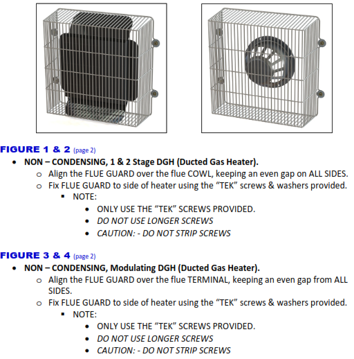
Non‑Condensing – 1 & 2 Stage DGH
- Position the flue guard over the flue cowl.
- Ensure there is an even gap on all sides of the flue outlet.
- Secure the flue guard to the side of the heater cabinet using:
- Supplied TEK screws
- Supplied washers
- Confirm the flue guard is firmly secured and correctly aligned.
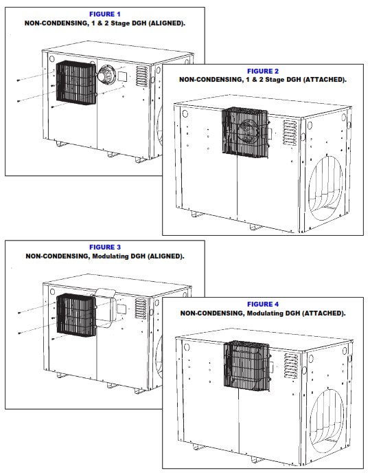
? Refer to Figure 1 (Aligned) and Figure 2 (Attached) in the mounting leaflet.
Non‑Condensing – Modulating DGH
- Position the flue guard over the flue terminal.
- Maintain an even clearance on all sides of the terminal.
- Fix the flue guard to the side panel of the heater using:
- Supplied TEK screws
- Supplied washers
- Verify the flue guard is secure and square to the terminal.
? Refer to Figure 3 (Aligned) and Figure 4 (Attached) in the mounting leaflet.
Important Installation Notes ⚠️
- ✅ Only use the TEK screws supplied with the kit
- ❌ Do not use longer screws
- ⚠️ Do not overtighten or strip screws
- ✅ The flue guard must not contact the flue or terminal
- ✅ Maintain clearance evenly on all sides
Failure to follow these instructions may result in appliance damage, reduced performance, or non‑compliance.
Visual Reference
For alignment and attachment detail, refer to Leaflet 616438e:
- Figure 1: 1 & 2 Stage DGH – Aligned
- Figure 2: 1 & 2 Stage DGH – Attached
- Figure 3: Modulating DGH – Aligned
- Figure 4: Modulating DGH – Attached