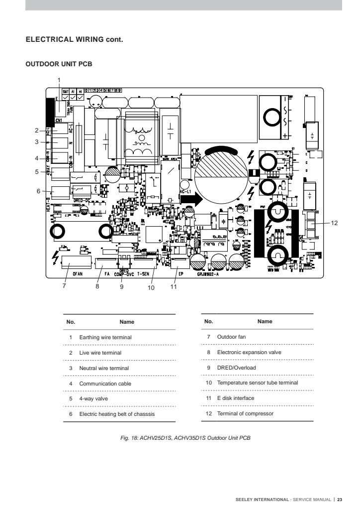
E6 Communication Malfunction - ASHV High Wall Split Systems
⚠️ Safety Notice
This information is intended only for suitably trained, qualified, licensed and authorised refrigeration and electrical service technicians.
Installation, commissioning, electrical work, refrigerant handling, servicing and repairs must be completed by personnel holding the licences, competencies and authorisations required by applicable legislation, regulations and industry requirements.
Before Commencing Work
- Complete a site-specific and task-specific risk assessment.
- Isolate electrical power before disconnecting wiring, measuring resistance or replacing components.
- Confirm safe isolation using an appropriate test instrument.
- Allow inverter capacitors to discharge according to the exact model’s service instructions.
- Confirm stored inverter voltage is at a safe level before touching outdoor electrical components.
- Use suitable PPE and insulated test equipment.
- Follow applicable working-at-height and roof-access requirements.
- Confirm the refrigerant type before connecting gauges, recovery equipment or charging equipment.
- Follow all additional requirements that apply to R32 flammable refrigerant systems.
- Keep ignition sources away from refrigerant work areas.
- Do not use oxygen or compressed air to pressure-test a refrigeration circuit.
- Do not bypass, modify or permanently disable pressure switches, overloads, float switches, sensors or other protective devices.
- Refit electrical covers, terminal covers and access panels before returning the system to service.
- Refer to the installation manual, service manual and wiring diagram applicable to the exact indoor and outdoor models.
Safety takes priority over diagnosis, repairs, installation schedules and customer expectations. Do not proceed if the task cannot be completed safely.
Fault Description
E6 - Communication Malfunction
E6 indicates the indoor and outdoor units are unable to communicate. This may be caused by incorrect model pairing, wiring faults, communication circuit failures, or failed indoor/outdoor PCBs.
Applicable Models
Indoor Units
- ASHV25D1S
- ASHV35D1S
- ASHV50D1S
- ASHV70D1S
- ASHV80D1S
Compatible Single-Split Outdoor Units
- ACHV25D1S
- ACHV35D1S
- ACHV50D1S
- ACHV70D1S
- ACHV80D1S
Important - Check Model Compatibility First
Before replacing PCBs or inspecting wiring, confirm the indoor and outdoor units belong to the same product series.
Single Split Systems
The indoor and outdoor units must be matched within the same series:
| Indoor Series | Outdoor Series |
|---|---|
| ASHV | ACHV |
| WSHV | WCHV |
| WSHV-T | WCHV-T |
Mixing series is not supported and may generate communication faults that cannot be resolved through wiring or PCB replacement.
Multi-Split Systems
NCHV and MCHV multi-head outdoor units may be paired with approved indoor unit series, however:
- All connected indoor units must be from the same series.
- Mixed-series indoor units must not be connected to the same multi-head outdoor unit.
Example: A WSHV indoor unit connected to an ASHV outdoor unit is not a valid combination and may report E6 communication faults.
Diagnostic Procedure
Step 1 - Power Reset
- Isolate power for 5 minutes.
- Restore power.
- Check if E6 returns.
If E6 returns immediately continue to Step 2.
Step 2 - Verify Model Compatibility
Confirm:
- Indoor model matches approved outdoor model series.
- Indoor and outdoor capacities are compatible.
- No mixed-series combinations are installed.
If models are incompatible, correct the installation before continuing.
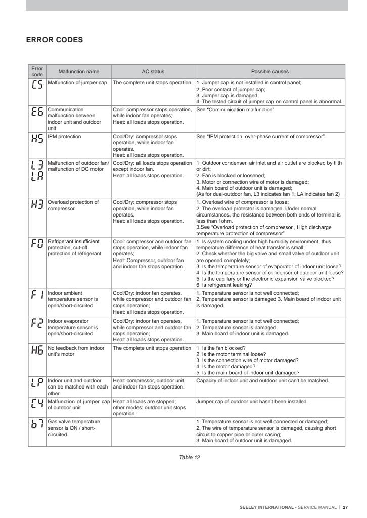
Step 3 - Check Indoor-to-Outdoor Wiring
Verify terminals match exactly:
| Terminal | Function |
|---|---|
| N(1) | Neutral |
| 2 | Communication |
| 3 | Active |
Inspect for:
- Loose terminals
- Incorrect terminal numbering
- Reversed conductors
- Damaged cable
- Corrosion
- Water ingress
Step 4 - Check Communication Cable
With power isolated:
- Disconnect terminal 2 at both ends.
- Test continuity.
- Check for shorts to:
- Neutral
- Active
- Earth
Expected result:
- Good continuity end-to-end.
- No shorts to other conductors.
Step 5 - Verify Supply Voltage
Measure at the outdoor unit:
| Test | Expected Reading |
|---|---|
| Active to Neutral | 218.5-253 VAC |
| Active to Earth | 218.5-253 VAC |
| Neutral to Earth | 0 VAC |
Power supply faults can interrupt communications.
Step 6 - Inspect PCB Communication Connections
Check both indoor and outdoor units for:
- Loose communication connectors
- Burnt terminals
- Moisture damage
- Corrosion
- Insect contamination
Step 7 - Follow Factory Flowchart
The service manual identifies the following fault path:
- Check indoor-to-outdoor wiring.
- Check wiring inside indoor and outdoor electrical boxes.
- Check outdoor communication circuit.
- Replace outdoor PCB if communication circuit is faulty.
- Replace indoor PCB if outdoor communication circuit tests correctly.
Common Field Findings
Most common causes of E6 are:
- Incorrect model pairing.
- Loose terminal 2 communication wire.
- Damaged interconnecting cable.
- Outdoor PCB failure.
- Indoor PCB failure.
Resolution
After repairs:
- Restore power.
- Operate the unit in cooling mode.
- Confirm E6 has cleared.
- Verify normal indoor and outdoor unit operation.
Related Articles
- LP - Indoor and Outdoor Unit Mismatch
- C5 - Jumper Cap Fault
- H6 - Indoor Fan Motor Fault
- E5 - AC Overcurrent Protection
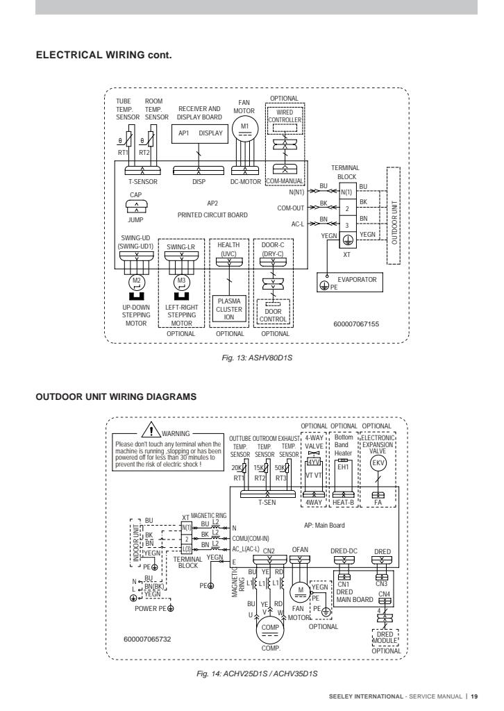
Inspect Internal Wiring
Remove power and inspect:
Indoor Unit
Verify:
- Communication wire securely connected
- PCB plugs fully seated
- No burnt connectors
- No damaged terminals
The communication terminal is identified on the indoor PCB.
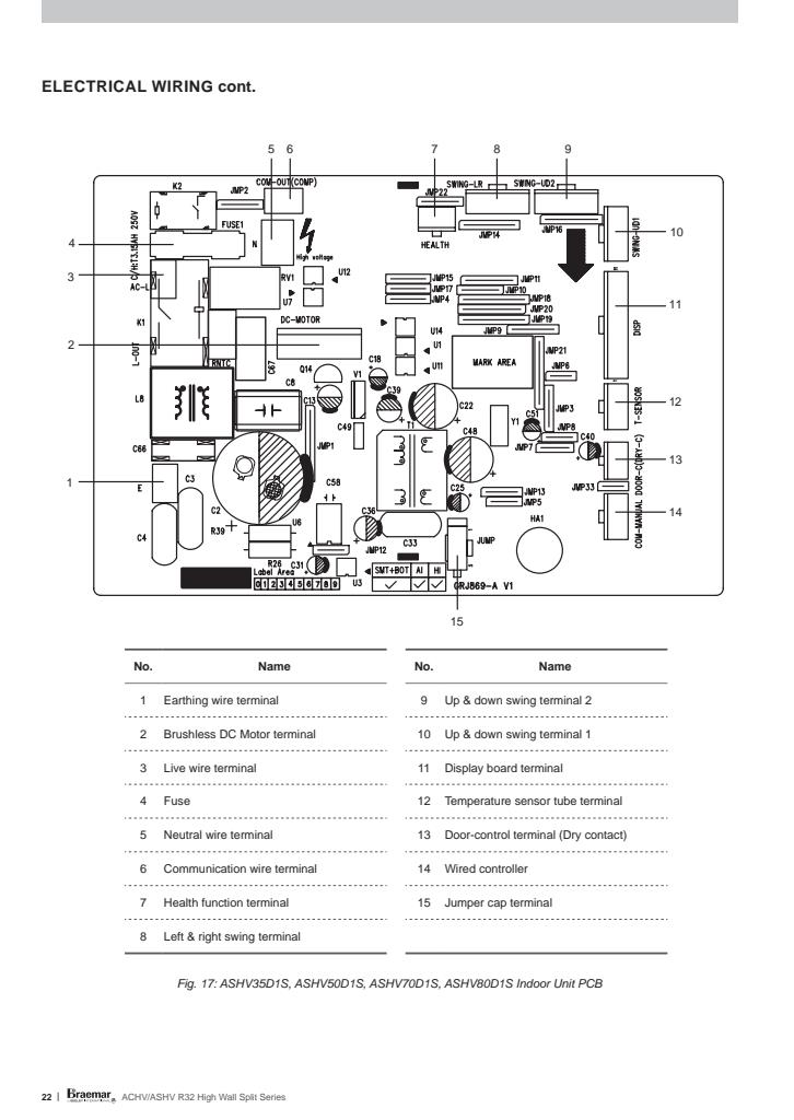
Outdoor Unit
Verify:
- Communication cable secure
- PCB connectors fully seated
- No signs of overheating
- No insect or moisture damage
The communication terminal is identified on the outdoor PCB.