⚠️ Safety Notice – Gas Heating Products
This appliance must only be installed, commissioned, serviced and repaired by suitably qualified and licensed personnel.
Before commencing work, complete a task-specific risk assessment and ensure gas and electrical safety requirements, ventilation provisions, safe access, adequate service clearances and appropriate PPE have been considered. All work must comply with applicable regulations, standards and manufacturer requirements.
Particular care must be taken when working around gas systems, electrical components, combustion products, hot surfaces, moving parts, roof spaces, ceiling spaces and confined spaces.
Do not proceed if safe access, required clearances, ventilation requirements, confined space risks or appropriate safety controls cannot be achieved and maintained.
Safety takes priority over diagnosis, repairs, installation schedules and customer expectations. If the task cannot be completed safely, it must not proceed until the risks have been adequately controlled.
FC4, FC10 & FC19 – High Temperature / Low Airflow Faults
Applies To
- Braemar TG / TH Series Gas Ducted Heaters
- FC4 – Thermistor >70°C During Run
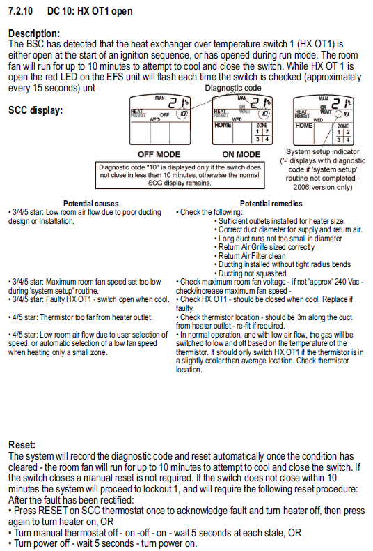
- FC10 – Heat Exchanger Over-Temperature Switch 1 (HX OT1) Open
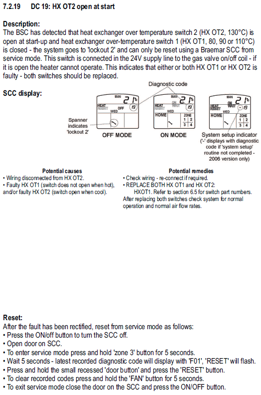
- FC19 – Heat Exchanger Over-Temperature Switch 2 (HX OT2) Open
What This Means
These faults are usually caused by the heater overheating because there is not enough airflow moving through the system.
When airflow is restricted, heat builds up inside the heater, and one or more safety devices operate to protect the appliance.
The fault may be caused by:
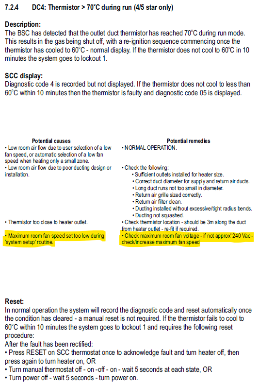
- Maximum fan speed set too low during commissioning
- Too few outlets installed for the heater size
- Restricted or undersized ductwork
- Blocked or dirty return air filter
- Incorrect thermistor location
- Faulty thermistor or over-temperature switch
- Damaged wiring to thermistor or HX switches
Quick Checks
1. Check Maximum Fan Speed
A common cause of FC4 and FC10 faults is the maximum system fan speed being set too low.
Verify that the maximum fan speed matches the number of installed outlets and heater size.
Important:
Do not assume you should measure 240 Vac at the fan motor.
The voltage supplied to the motor depends on:
- Maximum system fan speed setting
- Current fan speed being commanded by the controller
- Duct temperature
Refer to the fan speed voltage table at the end of this article.
If the measured voltage is significantly lower than expected, increase the maximum system fan speed setting and retest.
2. Check Number of Outlets
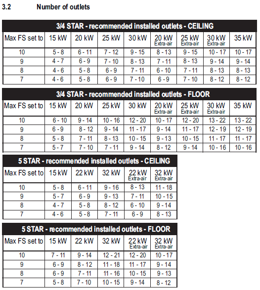
Confirm the system has sufficient supply outlets installed for the heater capacity.
Too few outlets can cause excessive duct temperatures and repeated overheating faults.
Refer to the installation manual outlet sizing chart.
3. Check Return Air System
Inspect:
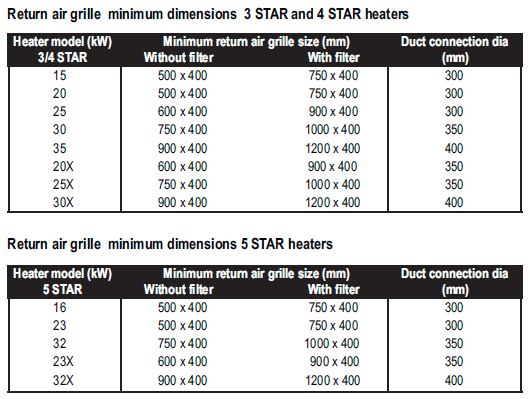
- Return air grille sizing
- Return air openings
- Return air filter cleanliness
A blocked filter or undersized return air system can significantly reduce airflow.
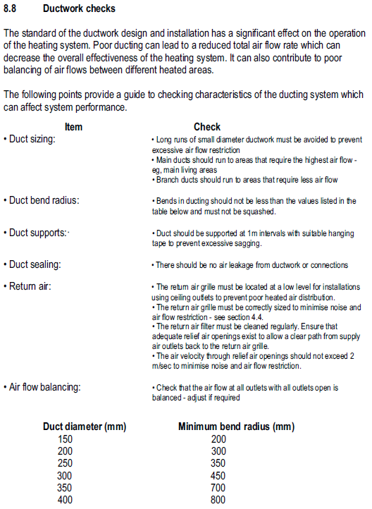
4. Inspect Ductwork
Check for:
- Crushed or kinked duct
- Excessive duct lengths
- Tight bends
- Poorly balanced airflow
- Disconnected ducting
Long runs of small diameter duct can restrict airflow and contribute to overheating.
5. Check Thermistor Location
For FC4 and FC10 faults:
The outlet duct thermistor should be installed approximately:
3 metres downstream from the heater outlet
If fitted too close to the heater, temperatures may be higher than normal and nuisance faults can occur.
6. Check Thermistor Operation
Applicable Parts:
| Model | Part Number |
|---|---|
| TH / THM Thermistor & Lead | 611136 |
| THMD Thermistor & Lead | 642796 |
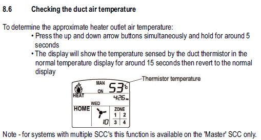
Using the wall controller:
- Check the displayed duct temperature.
- Confirm readings are realistic.
- Compare against actual duct temperature if required.
If the displayed temperature is excessively high when the duct is not hot, replace the thermistor.
7. Check HX Over-Temperature Switches
Applicable to FC10 and FC19.
Inspect:
- Wiring connections
- Switch continuity
- Signs of overheating
If an HX switch remains open when cool, replace the faulty switch.
Fault Specific Information
FC4 – Thermistor Above 70°C
The outlet duct temperature has exceeded 70°C during operation.
Most commonly caused by:
- Low airflow
- Fan speed set too low
- Incorrect thermistor location
FC10 – HX OT1 Open
The primary heat exchanger over-temperature switch has operated.
Most commonly caused by:
- Airflow restrictions
- Maximum system fan speed set too low
- Faulty HX OT1 switch
FC19 – HX OT2 Open At Start-Up
The secondary over-temperature switch is open when the heater starts.
Check:
- Wiring to HX OT2
- HX OT1 operation
- HX OT2 operation
If either switch is faulty, replace both switches as a pair.
After Repairs
After correcting the fault:
- Verify airflow is correct.
- Check maximum fan speed settings.
- Confirm duct temperature is normal.
- Clear fault history using the SCC controller if required.
- Test heater operation through a complete heating cycle.
Helpful Videos
Helpful Articles
- FC19 Fault Code – HX OT2 Opened Spectrolink Reset Procedure, FC10 History Check & Overheating Diagnosis (TG, TH, THM, THM5 & THM6): Seeley International Pty Ltd
- TG TH Spectrolink System Set Up including zone installation instructions: Seeley International Pty Ltd
Technician Tip
If FC4, FC10 or FC19 occur together, investigate airflow first. In most cases the root cause is insufficient airflow caused by incorrect fan speed settings, too few outlets, return air restrictions or ducting issues rather than a failed component.
Measuring Fan Motor Voltage (TG / TH Gas Heaters)
⚠️ Safety Warning – Authorised Technicians Only
Testing fan motor voltage requires working on live electrical equipment.
Before commencing:
- Isolate power before removing covers.
- Only restore power when taking measurements.
- Use a suitable, correctly rated multimeter.
- Keep clear of moving components and exposed electrical parts.
- Ensure safe access, particularly in roof spaces and ceiling cavities.
- Do not proceed if safe access or safe testing conditions cannot be maintained.
Important
Do not assume the fan motor should measure 240 Vac.
The voltage supplied to the motor varies depending on:
- The Maximum System Fan Speed set during commissioning.
- The fan speed currently being requested by the controller.
- The duct temperature measured by the thermistor.
As a result, a voltage reading below 240 Vac does not automatically indicate a fault.
How Fan Speed Control Works
When the heater starts:
- The burners ignite.
- The fan starts at a low speed.
- As the duct temperature increases, the controller gradually increases fan speed.
- The fan will continue increasing until it reaches the programmed Maximum System Fan Speed.
Step 1 – Check Maximum System Fan Speed
Before taking any voltage measurements, confirm the Maximum System Fan Speed setting.
The setting should match:
- Heater capacity
- Number of installed outlets
- Ducting design
A system with too few outlets or an incorrectly configured fan speed can experience:
- FC4 – Thermistor Above 70°C
- FC10 – HX OT1 Open
- FC19 – HX OT2 Open
due to reduced airflow.
Step 2 – Measure Motor Voltage
With the heater operating:
- Allow the heater to complete ignition.
- Allow the fan to stabilise.
- Measure AC voltage at the room fan motor output terminals on the control board.
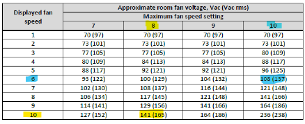
- Compare the reading to the expected voltage table below.
Example Readings
Example 1
Maximum Fan Speed = 10
Displayed Fan Speed = 6
Expected Motor Voltage ≈ 108 Vac
This is normal.
Example 2
Maximum Fan Speed = 8
Displayed Fan Speed = 10
Expected Motor Voltage ≈ 141 Vac
This is normal.
Interpreting Results
Voltage Lower Than Expected
If measured voltage is significantly lower than the table value:
Check:
- Maximum System Fan Speed setting
- Control board connections
- Wiring to the fan motor
- Fan motor operation
Voltage Matches Table
If measured voltage matches the table:
The control board is operating normally.
Investigate:
- Airflow restrictions
- Dirty return air filter
- Insufficient outlets
- Crushed or restricted ducting
- Thermistor location
- Thermistor operation
Technician Tip
When investigating FC4, FC10 or FC19 faults, always verify:
- Maximum System Fan Speed setting.
- Number of installed outlets.
- Return air condition.
- Ductwork restrictions.
- Thermistor location.
In many cases, overheating faults are caused by airflow problems rather than a faulty control board or fan motor.
Expected Fan Motor Voltage Reference
Compare your measured voltage against the applicable fan speed chart below based on the programmed Maximum System Fan Speed setting. A reading below 240 Vac can be completely normal and should only be considered in conjunction with the displayed fan speed and maximum fan speed setting.