⚠️ Safety Notice – Gas Heating Products
This appliance must only be installed, commissioned, serviced and repaired by suitably qualified and licensed personnel.
Before commencing work, complete a task-specific risk assessment and ensure gas and electrical safety requirements, ventilation provisions, safe access, adequate service clearances and appropriate PPE have been considered. All work must comply with applicable regulations, standards and manufacturer requirements.
Particular care must be taken when working around gas systems, electrical components, combustion products, hot surfaces, moving parts, roof spaces, ceiling spaces and confined spaces.
Do not proceed if safe access, required clearances, ventilation requirements, confined space risks or appropriate safety controls cannot be achieved and maintained.
Safety takes priority over diagnosis, repairs, installation schedules and customer expectations. If the task cannot be completed safely, it must not proceed until the risks have been adequately controlled.
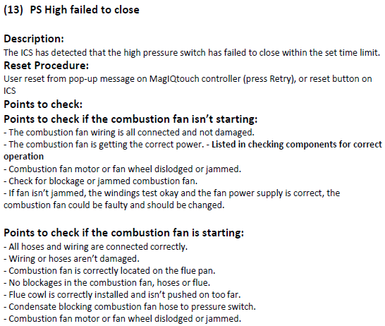
FC13 – PS High Failed to Close
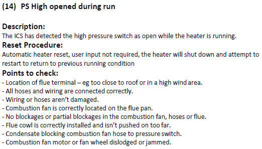
FC14 – PS High Opened During Run
READ THIS FIRST – Critical Understanding
FC13 does NOT mean a faulty pressure switch
The pressure switch is a safety sensor, not the cause of the issue.
- It is only reporting:
Insufficient combustion air suction pressure
In most cases, the fault is caused by:
- Airflow restriction
- Combustion fan / flue issue
- Hose or installation issue
Not a faulty pressure switch
Tech Tip
If the switch isn’t closing — combustion suction pressure isn’t being achieved
Do NOT replace the pressure switch first
Always check:
- Combustion fan
- Flue
- Pressure hoses
- Pressure tapping (spigot)
How the System Works
- Combustion fan starts
- Creates negative suction pressure (vacuum)
- Pressure pulls switch closed
- ICS confirms safe operation
If switch doesn’t close = pressure not achieved
Combustion fan → hose → pressure switch (open → closed)
Fault Logic
| Fault | Meaning |
|---|---|
| FC13 | Combustion Suction Pressure not achieved during start |
| FC14 | Combustion Suction Pressure lost during run |
IDENTIFYING PRESSURE SWITCHES (TQ HEATERS)
Important: Always refer to wiring diagram under heater lid before testing
System Configuration
- Single-stage heaters → 1 x High pressure switch
- Two-stage heaters→ 2 x switches:
- High pressure
- Low pressure
- Condensing heaters (plastic flue) → +1 condensate switch
Wiring Identification
| Switch | Wire Colours | ICS Connection |
|---|---|---|
| High Pressure | Blue + Red | Blue → Pin 11 |
| Low Pressure | Purple + Red | Purple → Pin 9 |
| Common Supply | Red | Pin 8 (24VAC) |
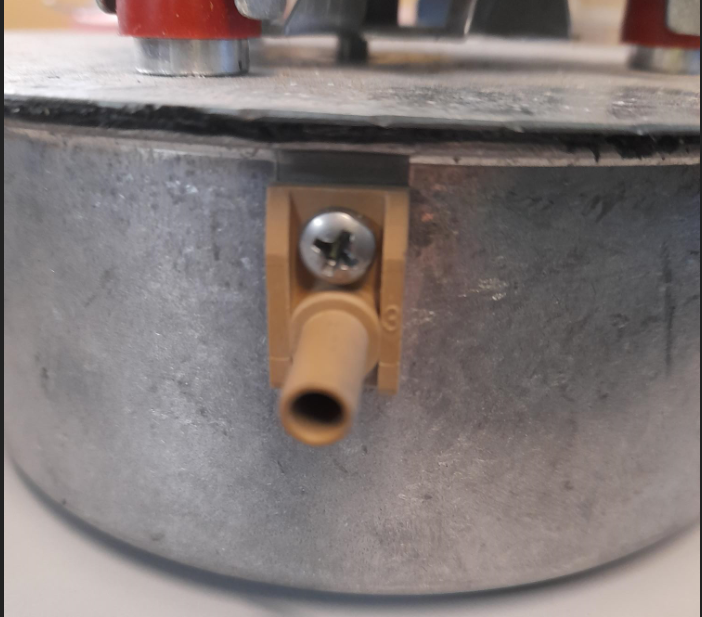
CRITICAL CHECK – Pressure Tapping (Spigot)
This is one of the MOST MISSED causes of FC13 / FC14
For ALL pressure switch faults:
Remove pressure hose from combustion fan
Inspect the pressure tapping (spigot)
Check for:
- Partial blockage inside the spigot
- Build-up from combustion by-products
- Restricted airflow through tapping point
A blocked spigot = false pressure reading → switch won’t close
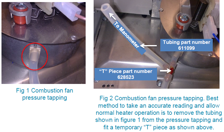
Combustion Fan Suction Pressure – Correct Testing Method
To accurately confirm the fault:
Measure suction pressure during normal operation (not static test)
Expected Result
- Pressure MUST be: Above pressure switch activation point - Ideally a minimum of ~20 Pa higher than switch rating
Example
- P100 switch → expect a minimum of approx. 120 Pa
- P80 switch → expect a minimum of approx. ~100 Pa
If pressure is:
- Correct → suspect switch
- Low → airflow / fan / restriction issue
Likely Causes (Check in Order)
1. Airflow / Flue Restriction (Most Common)
- Blocked flue
- Flue cowl pushed too far on
- Debris in combustion fan
- Condensate restriction
2. Combustion Fan Issues
- Not running or weak
- Fan wheel loose / jammed
- Poor sealing of combustion fan to Flue Pan (O ring seal has been pinched or perished)
3. Pressure Hose Issues
- Kinked or collapsed
- Loose fitting or split
- Water (condensate) in hose
- Disconnected or leaking
4. Installation Issues
- Panels not sealed
- Heater halves misaligned
- Air leaks affecting pressure
5. External Factors
- High wind
- Poor flue location
6. Pressure Switch (Last Check Only)
Only suspect if:
- Pressure is confirmed correct
AND - Switch does not change state
Step-by-Step Diagnostic Process
Step 1 – Check Combustion Fan
- Not running → fix fan first
- Running → continue
Click link below to view: 6.2 Combustion Fan Testing
Step 2 – Check Combustion Fan Suction Pressure
- Weak suction pressure → airflow issue
Not a switch fault
Step 3 – Inspect Hose & Spigot
- Remove hose
- Check:
- Hose condition
- Spigot (pressure tapping) on combustion fan blockage (critical)
Step 4 – Check Flue & Air Path
- Flue cowl
- Obstructions
- Combustion Fan mounting & seal
Step 5 – Check Heater Sealing
- Panels fitted correctly
- No air leaks
Step 6 – Confirm Pressure with Manometer
- Must exceed switch rating by a minimum of + ~20 Pa
Step 7 – Test Pressure Switch (Last Step)
- Apply pressure → should close
- Remove pressure → should open
If correct → switch is NOT faulty
When to Replace Parts
Pressure Switch
Replace ONLY if:
- Correct pressure confirmed
AND - Switch fails electrically
Combustion Fan
Replace if:
- Not operating
- Not generating pressure
Summary
- FC13 = No pressure achieved
- FC14 = Pressure lost during run
- Most faults = airflow / blockage / installation
Pressure switch is rarely the root cause
Always confirm pressure BEFORE replacing parts
Product Update – Pressure Switch Specification
As part of ongoing product development and continuous improvement activities, pressure switch specifications may vary across units and production periods.
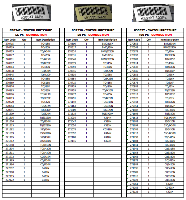
In some applications, a change from a 100 Pa pressure switch to an 80 Pa pressure switch has been introduced.
This update has been designed to maintain correct system operation and is backwards compatible with applicable heater models.
Service & Replacement Guidance
When replacing a pressure switch:
- Always confirm the correct switch rating (e.g. 80 Pa, 100 Pa)
- Refer to:
- Unit model
- Parts listing or service documentation
❗ Do NOT assume all units use the same pressure rating
Click link below to view:
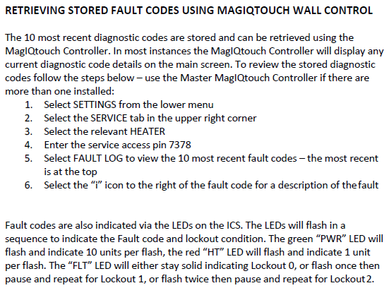
Fault code history can be accessed:
SETTINGS/SERVICE/GAS HEATER 01/7378 CONT/FAULT LOG
YouTube Video - MagIQtouch Heater Fault Log