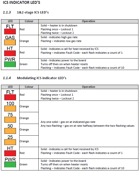
TQ / TQR DGH – FC32 & FC45 Combustion Air Pressure Too Low at Start or During Run
⚠️ Safety Notice – Gas Heating Products
This appliance must only be installed, commissioned, serviced and repaired by suitably qualified and licensed personnel.
Before commencing work, complete a task-specific risk assessment and ensure gas and electrical safety requirements, ventilation provisions, safe access, adequate service clearances and appropriate PPE have been considered. All work must comply with applicable regulations, standards and manufacturer requirements.
Particular care must be taken when working around gas systems, electrical components, combustion products, hot surfaces, moving parts, roof spaces, ceiling spaces and confined spaces.
Do not proceed if safe access, required clearances, ventilation requirements, confined space risks or appropriate safety controls cannot be achieved and maintained.
Safety takes priority over diagnosis, repairs, installation schedules and customer expectations. If the task cannot be completed safely, it must not proceed until the risks have been adequately controlled.
Click link below to view:
Fault Description
FC32 – Combustion Air Pressure Too Low at Start
The heater was unable to achieve the required combustion suction pressure during the startup sequence.
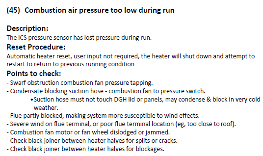
FC45 – Combustion Air Pressure Too Low During Run
The heater initially started correctly but lost combustion suction pressure during operation.
These faults are commonly caused by:
- Incorrect flue installation.
- Incorrect flue terminal/cowl selection.
- Excessive flue length or bends.
- Wind affecting the flue terminal.
- Restrictions in the flue system.
- Condensation or blockages in pressure sensing hoses.
- Air leaks in the combustion pressure sensing system.
Before replacing components, the complete flue system should be checked against the installation requirements.
Step 1 – Verify Combustion Pressure Testing Method
Before carrying out any pressure checks, ensure the manometer is connected correctly.
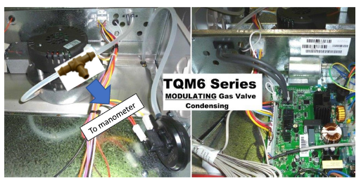
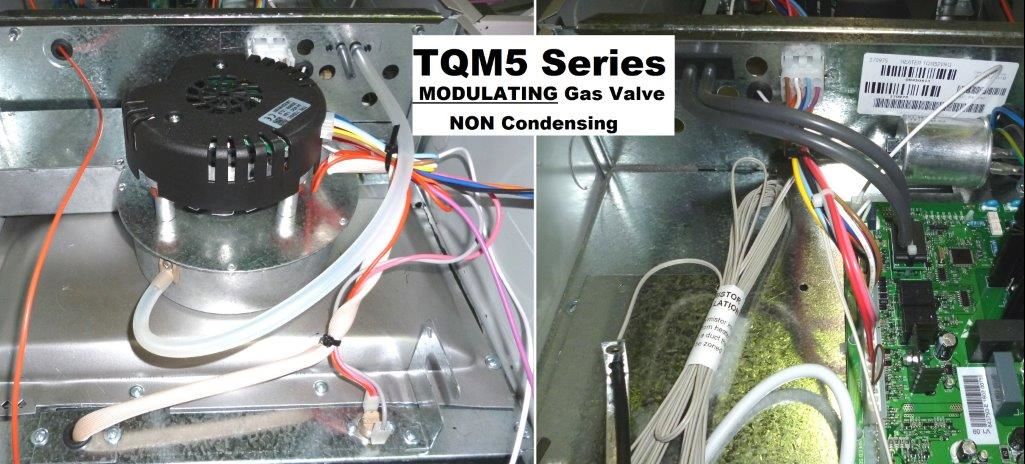
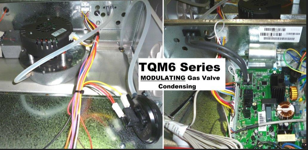
For TQR5/TQM5 and TQR6/TQM6 modulating heaters, combustion pressure must be measured using a T-piece fitted into the black combustion pressure sensing hose, not by connecting directly to the combustion fan pressure spigot.
Why This Is Important
The heater controls combustion fan speed using feedback from the pressure sensor. If the pressure sensor is disconnected during testing, the heater will continue increasing fan speed in an attempt to achieve the target pressure.
This can result in:
- Incorrect pressure readings.
- Misdiagnosis of the fault.
- Pressure values that do not represent normal heater operation.
Correct Testing Method
✅ Leave the pressure sensing system connected.
✅ Fit a temporary T-piece into the black suction hose.
✅ Connect the manometer to the T-piece.
✅ Measure the pressure being seen by the heater's pressure sensor.
Incorrect Testing Method
❌ Connecting a manometer directly to the combustion fan pressure spigot.
❌ Disconnecting the pressure sensor hose during testing.
Recommended Parts
The following spare parts can be used to create a temporary test point:
| Part Number | Description |
|---|---|
| 628806 | T-Piece Pressure Switch Fitting |
| 814803 | Pressure Switch Tube (5mm ID x 10mm) |
These components can be purchased through Spare Parts.
IMPORTANT
When testing a modulating heater, the pressure sensor must remain connected while the manometer is fitted.
If the pressure sensor is removed from the circuit, the combustion fan will continue ramping up in speed while trying to achieve the target pressure. Because the heater is no longer receiving pressure feedback, it will never know it has achieved the correct pressure, resulting in misleading readings.
Using a T-piece allows both the pressure sensor and the manometer to remain connected, ensuring the pressure being measured accurately reflects normal heater operation.
Combustion Pressure Guide (Pa)
| Heater Model | 25% | 50% | 75% | 100% |
|---|---|---|---|---|
| DEFAULT 5M | 85 | 135 | 210 | 290 |
| DEFAULT 6M | 88 | 120 | 195 | 320 |
| TQM 516 N | 74 | 110 | 175 | 275 |
| TQM 520 X N | 85 | 135 | 210 | 290 |
| TQM 530 X N | 85 | 115 | 205 | 290 |
| TQS 420 X N | 85 | 135 | 210 | 290 |
| TQS 430 X N | 70 | 90 | 145 | 250 |
| TQMD 516 N | 74 | 110 | 175 | 275 |
| TQMD 520 N | 85 | 135 | 210 | 290 |
| TQMD 530 N | 85 | 115 | 205 | 290 |
| SSQ 520 X N | 85 | 115 | 205 | 290 |
| SSQ 530 X N | 85 | 115 | 205 | 290 |
| TQM 18.6 N | 75 | 80 | 160 | 300 |
| TQM 623 X N | 85 | 95 | 188 | 320 |
| TQM 630 X N | 85 | 95 | 195 | 310 |
| TQS 523 X N | 85 | 95 | 188 | 320 |
| TQS 530 X N | 65 | 75 | 150 | 260 |
| TQS 623 X N | 85 | 120 | 175 | 260 |
| TQS 632 X N | 60 | 100 | 200 | 330 |
| TQS 720 N | 49 | 92 | 155 | 305 |
| TQS 730 N | 49 | 92 | 155 | 305 |
| TQM 520X U | 100 | 185 | 280 | 340 |
| TQM 530X U | 80 | 120 | 240 | 360 |
| TQM 623X U | 80 | 110 | 180 | 260 |
| TQM 630X U | 100 | 140 | 200 | 260 |
| TQM 520X P / TQMD 520XP | 86 | 142 | 262 | 335 |
| TQM 530X P / TQMD 530XP | 80 | 128 | 215 | 360 |
| TQM 6X23 P | 70 | 96 | 160 | 235 |
| TQM 6X30 P | 95 | 130 | 200 | 310 |
| TQA 530X N | 85 | 115 | 205 | 290 |
| TQA 632X N | 85 | 95 | 195 | 310 |
Notes
- These values are a guide only and should be measured using a T-piece installed in the combustion pressure sensing hose as described in Step 1.
- The pressure sensor must remain connected during testing on modulating heaters.
- Readings significantly below the expected value at any gas rate typically indicate a flue restriction, incorrect flue configuration, air leak, blocked pressure sensing hose, moisture contamination, combustion fan issue, or adverse wind effects.
Step 2 – Confirm the Correct Flue Terminal Has Been Fitted
Incorrect flue terminals can increase resistance and make the installation more susceptible to wind-related pressure faults.
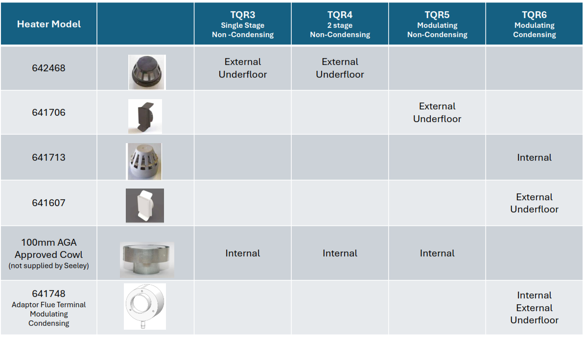
TQR5 / TQM5 Modulating Non-Condensing Heaters
External / Underfloor Installations
Flue Terminal P/N 641706.
Internal Installations
100mm AGA Approved Flue System with 100mm AGA Approved Cowl.
TQR6 / TQM6 Modulating Condensing Heaters
Internal Installations
Flue Terminal P/N 641713.
External / Underfloor Installations
Flue Terminal P/N 641607.
Adaptor Flue Terminal P/N 641748.
Step 3 – Check Flue Length and Number of Bends
TQR5 / TQM5 Modulating Non-Condensing Heaters
The installation manual specifies:
Maximum Flue Lengths
- Maximum vertical flue length: 4.8m
- Maximum horizontal flue length: 4m
- Maximum combined flue length: 6m
Maximum Bends
- Maximum 2 x 90° bends
- Two 45° bends are equivalent to one 90° bend
Flue Requirements
- Heater must be flued using 100mm AGA approved metal flue pipe.
- External socket joins must face downward.
- Internal socket joins must face upward.
- Flue joins must be adequately sealed.
- Twin-wall metal flue must be used where the flue is not readily accessible.
- Twin-wall metal flue is recommended on flue runs exceeding 2m.
Common Installation Issues
❌ Flue length exceeds maximum allowable limits.
❌ More than 2 × 90° bends installed.
❌ Additional bends added after commissioning.
❌ Incorrect flue pipe diameter used.
❌ Incorrect terminal/cowl fitted.
❌ Terminal location affected by wind turbulence.
❌ Partial blockage within the flue system.
TQR6 / TQM6 Modulating Condensing Heaters
The installation manual specifies:
Maximum Flue Lengths
- Maximum vertical rise: 5m
- Maximum total flue length: 12m
Maximum Bends
- Maximum 4 x 90° bends
- Two 45° bends are equivalent to one 90° bend
Flue Pipe Requirements
- Must be installed using 100mm DWV plastic pipe and fittings compliant with AS1260.
- Flue system must terminate using a 100mm DWV vent cowl.
- The flue terminal on the heater is designed to accept either:
- The male end of a 100mm DWV M-F elbow, or
- 100mm DWV pipe.
Flue Joint Requirements
All flue and condensate drain joints must be sealed using:
- Silicone sealant, or
- PVC solvent cement and primer.
Common Installation Issues
❌ Flue length exceeds the maximum allowable limits
❌ More than 4 × 90° bends installed
❌ Incorrect flue pipe size used
❌ Incorrect flue terminal or components used
❌ Flue terminal location affected by wind
❌ Partial blockage within the flue system
❌ Condensate drain installed incorrectly
❌ Moisture in the pressure sensing hose
❌ Pressure sensing hose contacting cold surfaces
The service manual specifically notes that the suction hose should not rest against the heater lid or panels where condensation can form and partially block the pressure signal.
Step 4 – Inspect the Complete Flue System
Inspect the entire flue system for any restriction to airflow, including insect nests, debris, partial blockages or incorrectly installed flue components.
Even a minor restriction can reduce combustion pressure and result in FC32 or FC45 faults.
Step 5 – Check Flue Terminal Location
Wind effects are one of the most common causes of intermittent FC45 faults.
Check whether the flue terminal is installed in a location susceptible to wind turbulence, such as:
- Near roof ridges.
- In roof valleys.
- Near tall walls.
- Close to nearby buildings or structures.
FC45 faults that occur mainly during windy conditions often indicate a flue terminal location issue.
Step 6 – Verify Flue Clearances
Minimum clearances from the flue terminal must be maintained.
Confirm the flue terminal complies with the minimum clearances specified in the installation manual.
Incorrect terminal clearances can contribute to wind-related combustion pressure faults in some installations.
Step 7 – Condensing Models Only (TQR6 / TQM6)
Moisture trapped in pressure sensing hoses can reduce the pressure signal seen by the ICS and generate FC32 or FC45 faults.
Step 8 – Inspect the Pressure Sensing System
Check:
- Pressure sensing hose.
- Hose joiners.
- Combustion fan pressure tapping.
- Pressure sensor connections.
Look for:
- Kinks.
- Splits.
- Cracks.
- Restrictions.
- Moisture contamination.
Any restriction between the combustion fan and the pressure sensor can affect the pressure reading seen by the ICS.
Step 9 – Inspect Heater Joins and Combustion Fan Sealing
Particularly on heaters that have been split during installation.
Check:
- Black joiner between heater halves.
- Combustion fan O-ring seal.
- Combustion fan mounting.
- Combustion fan locking tabs.
- Combustion fan sealing surfaces.
Look for:
- Cracks.
- Air leaks.
- Poor sealing.
- Damage to hose joiners.
Air leaks at these locations can reduce combustion suction pressure and generate FC32 or FC45 faults.
Before Replacing Components
Verify the following:
Confirm the flue installation complies with the installation requirements and that no issues have been found with:
- Flue length.
- Number of bends.
- Flue terminal selection.
- Flue terminal location.
- Restrictions within the flue system.
- Condensate drainage (TQR6/TQM6).
- Pressure sensing hoses and connections.
If all checks are satisfactory and FC32 or FC45 faults persist, further investigation of the combustion fan, pressure sensor or ICS may be required.
Click link below to view: 6.2 Combustion Fan Testing - 24 Vdc Combustion Fan (Modulating)
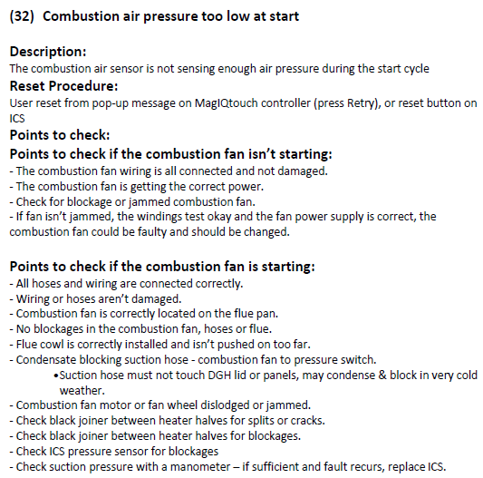
Check the ICS wiring loom plug connection:
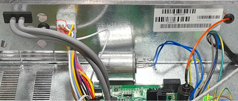
Ensure the brown wire (circled below) is securely connected and not causing a poor electrical connection. In some cases, the pin associated with the brown wire may need to be gently pulled through to fully engage, similar to the other pins in the plug.
Ensure the large white plug is making a secure electrical connection, particularly at the pin connected to the brown wire.
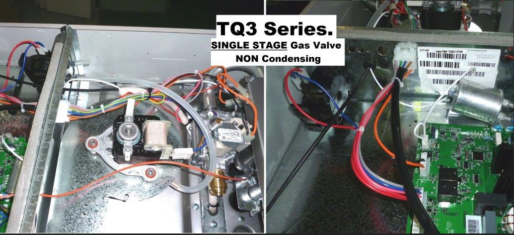
Fault code history can be accessed:
SETTINGS/SERVICE/GAS HEATER 01/7378 CONT/FAULT LOG
YouTube Video - MagIQtouch Heater Fault Log