TQ / TQR Zone Installation – MagIQtouch (Field Guide)
⚠️ Safety Notice – Gas Heating Products
This appliance must only be installed, commissioned, serviced and repaired by suitably qualified and licensed personnel.
Before commencing work, complete a task-specific risk assessment and ensure gas and electrical safety requirements, ventilation provisions, safe access, adequate service clearances and appropriate PPE have been considered. All work must comply with applicable regulations, standards and manufacturer requirements.
Particular care must be taken when working around gas systems, electrical components, combustion products, hot surfaces, moving parts, roof spaces, ceiling spaces and confined spaces.
Do not proceed if safe access, required clearances, ventilation requirements, confined space risks or appropriate safety controls cannot be achieved and maintained.
Safety takes priority over diagnosis, repairs, installation schedules and customer expectations. If the task cannot be completed safely, it must not proceed until the risks have been adequately controlled.
Applies to:
Braemar / Seeley TQ & TQR Series Gas Ducted Heaters with MagIQtouch zoning
Important:
This solution is provided as a supplementary guide and must be used in conjunction with the official installation instructions supplied with the MagIQtouch zone kit. Installers must follow all instructions provided with the kit to ensure correct and compliant installation.
Click link to view:
MagIQtouch Zone Control Installation Manual 863184-D: Seeley International Pty Ltd
Not all heaters are compatible with zoning.
TQ3 and TQR3 models cannot be zoned, as these units do not have the ability to modulate gas rates or fan outputs required for zoned operation.
Overview
This guide provides a practical installation and troubleshooting reference.
Primary focus (most installs):
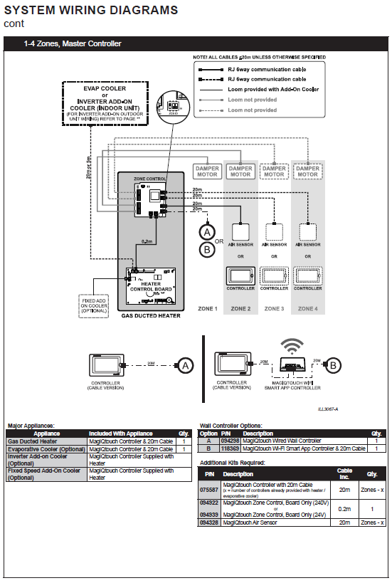
- 1–4 zones
- 24V zone motors/dampers
Safety Requirements
- Installation must be performed by qualified personnel
- Isolate power before working
STANDARD INSTALL (MOST COMMON)
1–4 Zones with 24V Dampers
Typical system:
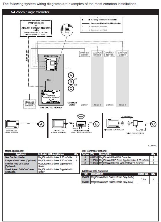
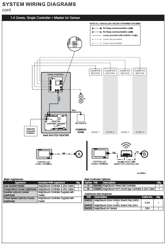
- 1 internal ZCB
- 24V dampers
- Transformer supplied
- Single controller
1. Mounting
- Install ZCB inside heater on standoffs
The zone board must be mounted on the plastic standoffs.
Do NOT rest it on the metal panel — this can cause short circuits and damage the board.
2. Power & Wiring (CRITICAL SECTION)
A. Zone Control Board (ZCB) POWER SUPPLY
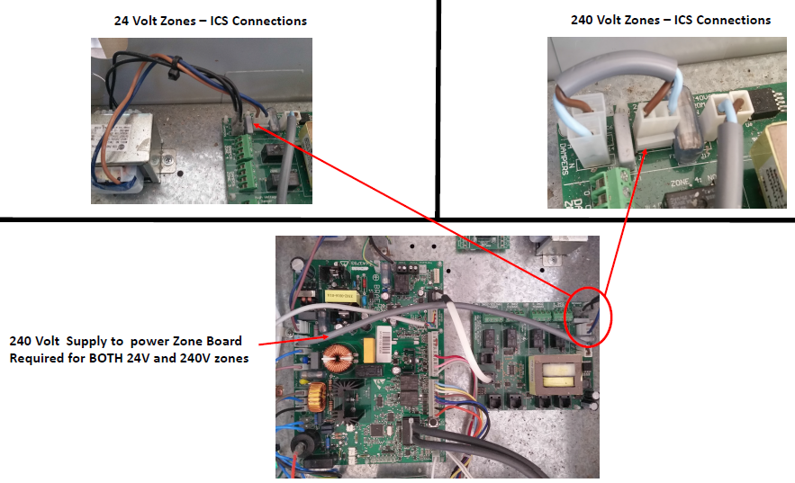
The zone board MUST be powered from the heater ICS board using the 350mm grey loom supplied in the kit.
Correct Connection
From Heater ICS board:
ZONE 240VAC(2-pin plug)
To Zone Control Board (ZCB):
- J16 & J17 (240VAC spade terminals)
This loom provides 240V supply to the ZCB
Critical Notes
- This connection is required for ALL systems (24V and 240V)
- Without this, the ZCB will not operate
- Common failure: loom not installed or missed during install
Field Symptom (If missing)
- No LED on zone board
- No zone operation
- No voltage output to dampers
Often incorrectly diagnosed as:
- Faulty ZCB
- Faulty damper motors
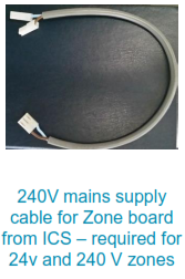
Zone PCB power connection / 350mm loom (ICS → J16/J17)
B. Communication Wiring
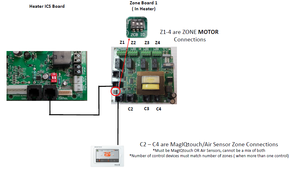
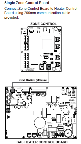
- Heater → ZCB (200mm cable)
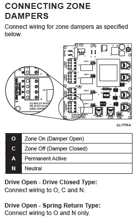
C. Damper Wiring
| Terminal | Function |
|---|---|
| O | Open |
| C | Close |
| N | Neutral |
Hardwired only
The RJ (plug-in) connections are for communication cables only (controllers and sensors).
Zone motors must be hardwired to the O, C & N terminals on the board, not plugged in.
HELPFUL INFORMATION - Various zone motor wiring colours
Click link to view - 24 Volt AC Zone Damper Motors Wiring Configurations Guide Only: Seeley International Pty Ltd
D. 24V Transformer Wiring (STANDARD)
- 240V → TRF input
- Output → DAMPER A & N
Supplies 24Vac
Do NOT use heater ICS main PCBA transformer
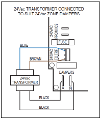
24V transformer wiring
3. DIP Switch Setup
- Zone switches → ON for each zone
- LED ON = zone open
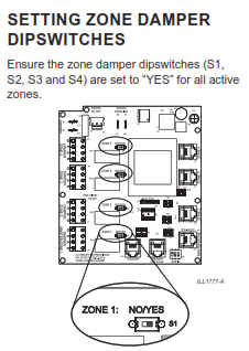
Zone PCB with DIP switches labelled
4. Minimum Outlets
- Must maintain minimum airflow
- Includes common + active zones
5. Commissioning
- Run MagIQtouch installation wizard
- Set zones and fan speeds
Zone Kit Types (24V vs 240V)
| Kit Type | Part Number | Voltage |
|---|---|---|
| 094922 | Board Only | 240V |
| 094939 | Board Only | 24V |
| 094908 | Enclosure | 240V |
| 094915 | Enclosure | 24V |
Click link to view:
TQ DGH 24 and 240 volt Zone Kits: Seeley International Pty Ltd
6. Troubleshooting (24V Focus)
No Zones Working (MOST COMMON)
Step 1 – CHECK THIS FIRST
Confirm:
- 350mm loom installed (ICS Zone 240VAC plug → 240VAC FROM ICS J16/J17 on Zone Board ZCB)
Step 2 – Check Transformer
- Measure:
- 24Vac at A & N on Zone Board ZCB
Diagnosis Logic
| Result | Fault |
|---|---|
| No ZCB LED | Missing 350mm loom |
| ZCB LED ON, no output | Transformer issue |
| Voltage present | Motor/wiring fault |
7. 240V and 5-10 zone Systems
240V Dampers
- Use jumper → DAMPER A & N
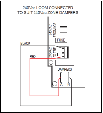
240V jumper wiring
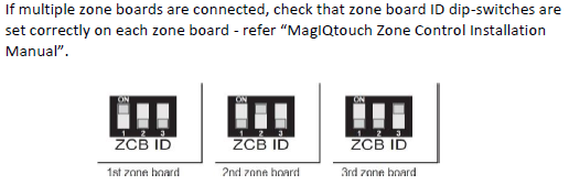
5–10 Zones
| Zones | Setup |
|---|---|
| 5–7 | 2 boards |
| 7–10 | 3 boards |
- Set ZCB IDs
- Daisy chain boards
System Reset / Re-Configuration
Click on link to view - MagIQtouch / Total System Reset - Single MagIQtouch Controller and Multiple MagIQtouch Controller: Seeley International Pty Ltd
Most Common Installation Issues
- 350mm loom not connected (MOST COMMON)
- Transformer not wired (24V)
- Missing jumper (240V)
- Dampers wired wrong
- ZCB ID duplicated
Pre-Commissioning Checklist
- 350mm loom connected (ICS → ZCB)
- ZCB powered (LED ON)
- Dampers wired correctly
- Transformer / jumper connected
- Zones enabled
Related Solutions
Click links to view