
Braemar TQ / TQM Fault Codes and ICS LED Flash Guide – Complete Diagnostics and Troubleshooting
⚠️ Safety Notice – Gas Heating Products
This information is intended only for suitably trained, qualified, licensed and authorised service technicians.
This appliance must only be installed, commissioned, serviced and repaired by personnel who hold the licences, competencies and authorisations required by applicable legislation, regulations and industry requirements.
Before commencing work:
- Complete an appropriate site-specific and task-specific risk assessment.
- Follow all applicable gas, electrical, working-at-height, confined-space and occupational health and safety requirements.
- Ensure safe access, adequate ventilation, required service clearances and suitable PPE are available.
- Isolate electrical power before disconnecting wiring, measuring resistance or replacing components.
- Do not bypass, modify or permanently disable safety devices or protection circuits.
- Confirm all wiring, pressure hoses, panels, seals and safety devices are correctly reinstated after servicing.
- Confirm gas pressure test points are closed, leak-free and safe before returning the heater to service.
- Do not operate the heater if flame rollout, combustion spillage, heat exchanger damage, unsafe combustion conditions or any other hazardous condition is suspected.
- Refer to the installation manual, service manual and technical documentation applicable to the exact heater model.
Particular care must be taken when working around gas systems, electrical components, combustion products, hot surfaces, moving parts, roof spaces, ceiling spaces and other confined or restricted work areas.
Do not proceed if safe access, required clearances, ventilation requirements, confined-space risks or appropriate safety controls cannot be achieved and maintained.
Important: The attending technician remains responsible for ensuring the appliance is left in a safe operating condition and complies with the manufacturer's instructions, applicable Australian Standards, gas installation and servicing requirements, local regulatory obligations and workplace safety requirements. This includes verifying the safe operation of combustion, flue system, gas and electrical systems, and completing any inspections, measurements or compliance checks required before returning the appliance to service.
Safety takes priority over diagnosis, repairs, installation schedules and customer expectations. If the task cannot be completed safely, it must not proceed until the risks have been adequately controlled.
Quick Navigation
TABLE OF CONTENTS - Click any heading below to jump to the relevant troubleshooting section
- Braemar TQ / TQM Fault Codes and ICS LED Flash Guide – Complete Diagnostics and Troubleshooting
- Before Commencing Diagnosis
- Retrieving Stored Fault Codes
- Reading Fault Codes from the ICS LEDs
- Lockout Levels and Reset Procedures
- No Fault Code, No Display or Heater Not Found
- Pressure Switch & Condensate Faults
- Thermistor & Temperature-Sensing Faults
- Ignition, Flame-Sensing & Rollout Faults
- FC6 – Flame Detected When Not Required
- FC07 – Ignition Failure
- FC11 – Loss of Flame Signal
- FC20 – Flame Rollout Detected During Start
- FC21 – Flame Rollout Detected During Run
- FC35 – Flame Rollout Circuit Check Failed
- FC36 – Flame Rollout Circuit Disconnected or Shorted
- FC48 – Micro Flame Mismatch
- FC70 to FC78 – ICS Flame Circuit Monitoring Faults
- FC70, FC71, FC74, FC75 & FC78
- FC72 & FC76
- FC73 & FC77
- Over-Temperature Protection Faults
- Room Fan Faults
- Configuration & Wiring Loom Faults
- Combustion Air Pressure & Combustion Fan Faults
- Gas Valve & Gas Control Faults
- Electrical, Communication & Internal ICS Faults
- Final Service Checks
Introduction
This guide helps qualified service technicians quickly diagnose and resolve fault codes on Braemar gas ducted heaters fitted with an Integrated Control System (ICS).
Applicable models include TQ, TQM, TQS, TQD, TQMD, TQA, BMQ and SSQ series heaters.
First, retrieve the fault history from the MagIQtouch Controller or identify the fault using the ICS LED flash sequence. Then use the Table of Contents to jump directly to the relevant fault code.
Each fault section includes:
- Fault description
- Reset requirements
- Common causes
- Diagnostic checks
Important: Always diagnose the cause of the fault before replacing components. Once repairs are complete and correct operation is confirmed, clear the stored fault history.
Before Commencing Diagnosis
Before replacing any parts:
- Ask the customer what the heater is doing and when the fault occurs.
- Record the current fault code and fault history.
- Note the date and time of any repeat faults.
- Confirm the correct heater model and serial number are shown in MagIQtouch.
- Check for loose wiring, disconnected hoses, moisture, corrosion, dirt or visible damage.
- Ensure all panels, seals and combustion components are fitted correctly.
- Verify the heater has power and gas supply.
- Test the suspected component before replacing it.
- After repairs, run the heater through a complete heating cycle.
- Clear the fault history once correct operation is confirmed.
Important: Only replace components that have failed testing. Record fault details and test results on the service report for warranty and technical analysis purposes
| Fault Code | Fault Group |
|---|---|
| No Code / Heater Not Found | Power, Communication & Controller Faults |
| FC01-FC03 | Low Pressure Switch Faults |
| FC04-FC05 | Thermistor & Temperature Sensing Faults |
| FC06-FC07 | Ignition & Flame Detection Faults |
| FC08-FC09 | Condensate & Thermistor Startup Faults |
| FC10 | HX OT1 Over-Temperature Fault |
| FC11 | Loss of Flame Signal |
| FC12-FC14 | High Pressure Switch Faults |
| FC15-FC16 | Thermistor Location / Installation Faults |
| FC17-FC18 | Condensate Drainage Faults |
| FC19 | HX OT2 Over-Temperature Fault |
| FC20-FC21 | Flame Rollout Faults |
| FC22 | Supply Voltage Fault |
| FC23-FC24 | Room Fan Faults |
| FC25-FC30 | Configuration & Wiring Loom Faults |
| FC31-FC32 | Combustion Air Pressure Faults |
| FC33 | Internal ICS Heat Enable Fault |
| FC34 | Gas Valve On/Off Fault |
| FC35-FC36 | Rollout Circuit Faults |
| FC37 | ICS Reset Button Fault |
| FC38 | Gas Valve Closed During Run |
| FC39 | Combustion Pressure Sensor Fault |
| FC45 | Combustion Pressure Too Low During Run |
| FC46 | Modulating Gas Valve Fault |
| FC47 | Pressure Sensor Communication Fault |
| FC48 | Micro Flame Mismatch |
| FC49 | Repeated Lockouts |
| FC50 | MagIQtouch Communication Fault |
| FC51-FC53 | ICS Processor, Memory & Voltage Faults |
| FC54-FC63 | Internal ICS Faults |
| FC64 | Combustion Fan Fault |
| FC70-FC78 | Flame Circuit Monitoring Faults |
Quick Navigation
- Pressure Switch Faults: FC01, FC02, FC03, FC08, FC12, FC13, FC14
- Thermistor Faults: FC04, FC05, FC09, FC15, FC16
- Ignition & Flame Faults: FC06, FC07, FC11, FC20, FC21, FC48, FC70-FC78
- Over-Temperature Faults: FC10, FC19
- Fan Faults: FC23, FC24, FC64
- Gas Valve Faults: FC34, FC38, FC46
- Combustion Pressure Faults: FC31, FC32, FC39, FC45, FC47
- Communication & ICS Faults: FC22, FC33, FC37, FC49-FC63
- Configuration Faults: FC25-FC30
Tip: Before starting diagnosis, check the Fault Log (Settings → Service → Heater → 7378 → Fault Log) and identify the earliest recurring fault code. In most cases, this is the root cause of the problem, while later fault codes are often secondary faults generated as a result of the original issue.
⚠️ Important: After repairs and successful testing, clear the fault history before leaving site. This helps ensure future fault logs accurately reflect new issues and prevents previous fault codes causing confusion during subsequent service visits.
Retrieving Stored Fault Codes
The system stores the 10 most recent diagnostic codes.
Using the Master MagIQtouch Controller:
- Select SETTINGS.
- Select the SERVICE tab.
- Select the relevant HEATER.
- Enter service PIN 7378.
- Select FAULT LOG.
- The most recent fault appears at the top.
- Select the information icon beside a fault for its description.
Always review the complete fault history. A later lockout may be the result of an earlier fault rather than the original cause.
YouTube Video - Accessing MagIQtouch Heater Fault Log
YouTube Video - MagIQtouch Service Operating Screen Ducted Gas Heater
Reading Fault Codes from the ICS LEDs
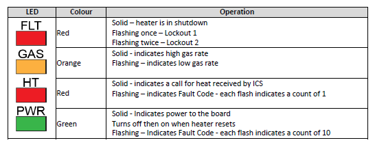
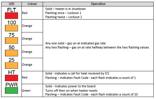
The ICS LEDs can identify both the fault code and lockout level:
- Green PWR LED: Each flash represents 10.
- Red HT LED: Each flash represents 1.
- Red FLT LED: Indicates the lockout condition.
For example:
- PWR flashes once = 10
- HT flashes eight times = 8
- Fault code = FC18
The indicator arrangements vary between single-stage, two-stage and modulating ICS boards. Confirm which ICS is fitted before interpreting gas-rate LEDs.
YouTube Video - Reading ICS LEDs to determine Fault Code
Lockout Levels and Reset Procedures
L0 – Automatic Reset
The heater records the fault, shuts down and automatically attempts to return to operation. User input is normally not required.
L1 – User Reset Required
Reset by either:
- Selecting Retry on the MagIQtouch Controller; or
- Pressing the ICS RESET button for 1 to 2 seconds, then releasing it.
L2 – Service Reset Required
Reset by either:
- Select SETTINGS.
- Select SERVICE.
- Select the relevant heater.
- Enter 7378.
- Select RESET LOCKOUT STATUS.
Alternatively, press the ICS RESET button for 1 to 2 seconds and release it.
Do not repeatedly reset a heater without identifying the cause of the lockout.
No Fault Code, No Display or Heater Not Found
MagIQtouch Controller Blank Screen
- Check all communication cable connections.
- Inspect the communication loom for damage.
- Connect the controller using a known-good test lead.
- If it works with the test lead, repair or replace the installed loom.
- If still blank, check heater power and ICS operation.
- If available, test with a known-good controller.
No LEDs on the ICS
- Confirm 230 VAC supply to the heater.
- Confirm 230 VAC to the transformer.
- Confirm 24 VAC output from the transformer.
- Isolate power and check all ICS fuses.
- Replace fuses with the correct type and rating only.
- If a fuse blows again, find the cause before replacing it again.
PWR LED On, HT LED Off
- Confirm the controller is calling for heat.
- Increase the setpoint above room temperature.
- Check controller communication.
- Confirm the correct model and serial number are programmed.
- Check any manual thermostat is connected correctly.
Heater Not Found
- Check all MagIQtouch communication connections.
- Ensure communication cables are separated from mains wiring.
- Test with a known-good short communication lead.
- If fitted, test directly at the zone board.
- Check the connection between the zone board and ICS.
- Connect directly to the ICS to isolate loom, controller or zone board faults.
- Perform a full system reset only after all wiring and components have been checked.
Tip: Always use a known-good test lead before replacing controllers, looms, zone boards or the ICS.
Common Component Checks
Thermistor
The outlet thermistor must be installed approximately 3 metres along the supply-air duct in a location with constant airflow. It must not be installed in the return-air duct or in a zone that can be closed off. The thermistor is used by the ICS to monitor outlet-air temperature and control room fan operation.
Before replacing a thermistor:
Thermistor Check
- Open the Service Operating Screen and record the THERM (thermistor temperature) value reported by the ICS.
- Disconnect the thermistor from the ICS.
- Immediately measure resistance across the thermistor terminals.
- Compare the measured resistance to the recorded thermistor temperature using the table above.
- If the resistance does not reasonably correspond with the recorded temperature, inspect the thermistor and wiring before replacement.
| Temperature | Resistance |
|---|---|
| 10°C | 6.6 kΩ |
| 15°C | 5.1 kΩ |
| 20°C | 4.2 kΩ |
| 25°C | 3.3 kΩ |
| 30°C | 2.7 kΩ |
| 40°C | 1.8 kΩ |
| 50°C | 1.2 kΩ |
| 70°C | 580 Ω |
Note: The thermistor is an NTC (Negative Temperature Coefficient) sensor. As temperature increases, resistance decreases. Readings that do not reasonably correspond to the measured outlet-air temperature may indicate a faulty thermistor, damaged wiring or poor connections.
YouTube Video MagIQtouch Service Operating Screen Ducted Gas Heater
Minimum Gas Inlet Pressure
Check with the heater and all other gas appliances operating at maximum load:
- Natural Gas: Minimum 1.13 kPa
- Propane: Minimum 2.75 kPa
Always verify the required burner test point pressure from the heater data label.
Combustion Fan Checks
Check:
- Fan wheel spins freely
- Fan housing and seals are fitted correctly
- Wiring is secure
- Correct voltage is present
- Pressure hoses and tappings are clear
- Fan wheel and motor are secure and not slipping
Room Fan Checks
Check:
- Fan wheel spins freely with power isolated
- Wheel is secure on the shaft
- Wiring matches the heater wiring diagram
- Capacitor tests close to its rated value
- Motor windings are not open circuit
- Speed sensor (if fitted) is secure
- Correct voltage is supplied from the ICS
IMPORTANT!!! Helpful Solution Article links:
Braemar TQ Gas Heater Component Testing & Fault Diagnosis TQ Service Guide 2023 (644066M)
Pressure Switch & Condensate Faults
Typical causes: Blocked flues, restricted hoses, condensate, wind effects, faulty pressure switches, combustion fan issues, or installation problems. Always inspect the complete pressure and airflow path before replacing components.
FC1 – PS Low Closed at Start
Summary: Low pressure switch is closed before the combustion fan starts.
Reset: Retry or press ICS RESET.
Check:
- Pressure hose for kinks, water or damage
- Combustion fan pressure tapping for blockage
- Wiring for shorts or damage
- Switch is open circuit with no pressure applied
- Correct switch pressure rating fitted
- Panels, joins and seals fitted correctly
- Excess supply air entering combustion chamber
Replace the switch only if it remains closed with no pressure applied.
IMPORTANT!!! Helpful Solution Article links:
Braemar TQ Gas Heater Component Testing & Fault Diagnosis TQ Service Guide 2023 (644066M)
FC2 – PS Low Failed to Close
Summary: Low pressure switch did not close after combustion fan started.
Reset: Retry or ICS RESET.
If combustion fan is NOT running:
- Check wiring and connectors
- Check fan is not jammed
- Confirm correct voltage to fan
- Test fan motor/windings
If combustion fan IS running:
- Check hoses for splits, kinks or condensate
- Check fan seal and mounting
- Check flue, pressure tappings and fan for blockage
- Check flue cowl installation
- Measure switch operating pressure
- Test switch operation
Replace the switch only if correct pressure is present and the switch will not close.
Helpful Solution Article links:
Braemar TQ Gas Heater Component Testing & Fault Diagnosis TQ Service Guide 2023 (644066M)
FC3 – PS Low Opened During Run
Summary: Low pressure switch opened during operation.
Reset: Automatic (L0).
Check:
- Wind effects at flue terminal
- Partial flue blockage
- Condensate in sensing hose
- Damaged hoses or fittings
- Combustion fan wiring and connections
- Fan wheel damage or slipping
- Two-stage fan resistor (if fitted)
- Panel seals and joins
- Operating pressure remains stable throughout the cycle
Helpful Solution Article links:
Braemar TQ Gas Heater Component Testing & Fault Diagnosis TQ Service Guide 2023 (644066M)
FC8 – PS Condensate Closed at Start
Summary: Condensate pressure switch closed before startup.
Reset: Retry or ICS RESET.
Check:
- Switch is open circuit with no pressure applied
- Condensate hose for blockage or retained water
- Hose routing has continuous fall
- Correct switch rating fitted
- Drain and flue installation
- Wind effects on flue terminal or drain
Replace the switch if it remains closed with hoses removed.
Helpful Solution Article links:
TQ DGH - FC8, FC17 and FC18 Condensate detected
FC12 – PS High Closed at Start
Summary: High pressure switch is closed before startup.
Reset: Retry or ICS RESET.
Check:
- High pressure hose for damage or condensate
- Wiring for shorts or damage
- Switch is open circuit with no pressure applied
- Correct pressure switch fitted
- Pressure tappings are clear
Replace the switch if it remains closed with no pressure applied.
FC13 – PS High Failed to Close
Summary: Combustion pressure was insufficient to close the high-pressure switch.
Reset: Retry or ICS RESET.
Check:
- Combustion fan operation
- Hoses and electrical connections
- Fan mounting and seals
- Pressure tappings and flue for blockage
- Flue cowl installation
- Condensate in sensing hose
- Fan wheel condition
- Available operating pressure
Replace the switch only if correct pressure is available and the switch will not close.
Helpful Solution Article links:
TQ / DGH FC13 – PS High Failed to Close | FC14 Pressure Fault – Causes & Fix
FC14 – PS High Opened During Run
Summary: High pressure switch opened while running.
Reset: Automatic (L0).
Check:
- Wind effects at flue terminal
- Hoses, wiring and connectors
- Fan mounting tabs and sealing O-ring
- Flue, fan and hose restrictions
- Condensate in sensing hose
- Fan wheel or motor intermittently failing
- Operating pressure throughout heating cycle
Helpful Solution Article links:
TQ / DGH FC13 – PS High Failed to Close | FC14 Pressure Fault – Causes & Fix
FC17 – Condensate Detected During Run
Summary: Condensate safety circuit detected retained water during operation.
Reset: Automatic (L0).
Check:
- Drain plugs removed during installation
- Drain line has continuous fall
- Drain is not blocked, sagging or trapped
- Heater is level
- Correct drain kit installed
- Drain outlet cannot flood or block
- Drain line freezing (cold climates)
- Pressure switch hoses and drain connections
- Condensate drains freely during operation
Helpful Solution Article links:
TQ DGH - FC8, FC17 and FC18 Condensate detected
FC18 – Condensate Detected During Start
Summary: Condensate detected before ignition.
Reset: Retry or ICS RESET.
Check:
- All FC17 drain checks
- Water retained from previous cycle
- Water trapped in hoses or switch
- Switch returns to normal after draining
- Drain pan and outlet are clear
- Heater drains completely after operation
Helpful Solution Article links:
TQ DGH - FC8, FC17 and FC18 Condensate detected
Technician Tip: For FC01, FC02, FC03, FC12, FC13 and FC14, most faults are caused by blocked flues, blocked pressure tappings, condensate in hoses, poor fan sealing or wind-affected flue installations rather than a faulty pressure switch. Always verify pressure and airflow before replacing parts.
Thermistor & Temperature-Sensing Faults
Note: Thermistor faults can be caused by a faulty sensor, wiring issue, poor airflow, incorrect thermistor location, or unsuitable duct design. Always check the installation before replacing the thermistor.
FC4 – Thermistor Above 70°C During Run
Summary: Outlet air temperature exceeded 70°C during operation.
Reset: Automatic.
Check:
- Maximum fan speed is not set too low.
- Thermistor is installed approximately 3 m along the supply air duct.
- Thermistor is in a constant airflow duct that cannot be zoned off.
- Thermistor reading matches resistance:
- 10°C = 6.6 kΩ
- 15°C = 5.1 kΩ
- 20°C = 4.2 kΩ
- 25°C = 3.3 kΩ
- 30°C = 2.7 kΩ
- 50°C = 1.2 kΩ
- 70°C = 580 Ω
- Thermistor wiring and connections.
- Sufficient outlets are open for the heater size.
- Duct sizing, crushed duct, tight bends, or long undersized runs.
- Return air grille size and filter condition.
- Room fan operation, capacitor, and motor.
- Burner pressure and gas rate match the data plate.
Most common cause: Restricted airflow rather than a faulty thermistor.
IMPORTANT!!! Helpful Solution Article links:
TQ DGH - FC4, FC5, FC9, FC15 and FC16 Thermistor related faults
Braemar TQ Gas Heater Component Testing & Fault Diagnosis TQ Service Guide 2023 (644066M)
YouTube Video MagIQtouch Service Operating Screen Ducted Gas Heater
FC5 – Thermistor Short or Open Circuit
Summary: Thermistor reading is outside the expected range.
Reset: Retry or ICS RESET.
Check:
- Thermistor plug connection at the ICS.
- Sensor and cable for damage.
- Thermistor resistance matches actual temperature.
- 10°C = 6.6 kΩ
- 15°C = 5.1 kΩ
- 20°C = 4.2 kΩ
- 25°C = 3.3 kΩ
- 30°C = 2.7 kΩ
- 50°C = 1.2 kΩ
- 70°C = 580 Ω
- Wiring continuity between thermistor and ICS.
- Damaged terminals or loose connections.
- Duct temperature is not below -10°C.
Replace the thermistor only if resistance does not match temperature.
IMPORTANT!!! Helpful Solution Article links:
TQ DGH - FC4, FC5, FC9, FC15 and FC16 Thermistor related faults
Braemar TQ Gas Heater Component Testing & Fault Diagnosis TQ Service Guide 2023 (644066M)
YouTube Video MagIQtouch Service Operating Screen Ducted Gas Heater
FC9 – Thermistor Above 60°C During Start
Summary: Thermistor temperature exceeded 60°C before the heating cycle started.
Reset: Automatic.
Check:
- Recent power interruption prevented the fan cool-down cycle.
- Thermistor connection and wiring.
- Thermistor installed approximately 3 m along the supply air duct.
- Thermistor resistance matches displayed temperature.
- 10°C = 6.6 kΩ
- 15°C = 5.1 kΩ
- 20°C = 4.2 kΩ
- 25°C = 3.3 kΩ
- 30°C = 2.7 kΩ
- 50°C = 1.2 kΩ
- 70°C = 580 Ω
- Residual heat trapped by closed zones or restricted ductwork.
- Room fan completed its shutdown cycle.
Investigate recurring faults rather than repeatedly resetting the system.
IMPORTANT!!! Helpful Solution Article links:
TQ DGH - FC4, FC5, FC9, FC15 and FC16 Thermistor related faults
Braemar TQ Gas Heater Component Testing & Fault Diagnosis TQ Service Guide 2023 (644066M)
YouTube Video MagIQtouch Service Operating Screen Ducted Gas Heater
FC15 – Thermistor in Cool Duct Location
Summary: Thermistor is not sensing representative heated air and repeated temperature-limit faults have occurred.
Reset: Automatic.
Check:
- Thermistor installed approximately 3 m from the heater outlet.
- Thermistor is in the heated supply air stream.
- Thermistor is not in return air.
- Thermistor is not located in a duct or zone that can be closed.
- Airflow passes the sensor whenever the heater operates.
- Thermistor resistance matches actual temperature.
- Wiring and terminals are secure.
Relocate the thermistor if it is installed in an unsuitable location.
IMPORTANT!!! Helpful Solution Article links:
TQ DGH - FC4, FC5, FC9, FC15 and FC16 Thermistor related faults
Braemar TQ Gas Heater Component Testing & Fault Diagnosis TQ Service Guide 2023 (644066M)
YouTube Video MagIQtouch Service Operating Screen Ducted Gas Heater
FC16 – Thermistor Not Installed in Outlet Duct
Summary: The ICS did not detect the expected outlet air temperature rise.
Reset: Retry or ICS RESET.
Check:
- Thermistor is installed in the outlet duct.
- Thermistor has not fallen out or been pulled from the airflow.
- Thermistor is approximately 3 m along the supply air duct.
- Thermistor is in a duct that cannot be zoned off.
- Thermistor wiring and ICS connection.
- Thermistor resistance matches actual duct temperature.
- Burner operation and heated airflow reach the sensor.
- For systems with add-on cooling and later ICS software, confirm the second thermistor is installed and connected correctly.
After repairs, run the heater through a complete heating cycle to confirm correct operation.
IMPORTANT!!! Helpful Solution Article links:
TQ DGH - FC4, FC5, FC9, FC15 and FC16 Thermistor related faults
YouTube Video MagIQtouch Service Operating Screen Ducted Gas Heater
Technician Tip: Before replacing a thermistor, always compare the displayed temperature with the measured resistance. Many FC04, FC09, FC15 and FC16 faults are caused by airflow, zoning, ductwork or installation issues rather than the thermistor itself.
- Disconnect the thermistor from the ICS.
- Measure thermistor resistance using a multimeter set to the Ohms (Ω) range.
- Compare the measured resistance against the actual temperature.
- 10°C = 6.6 kΩ
- 15°C = 5.1 kΩ
- 20°C = 4.2 kΩ
- 25°C = 3.3 kΩ
- 30°C = 2.7 kΩ
- 50°C = 1.2 kΩ
- 70°C = 580 Ω
Ignition, Flame-Sensing & Rollout Faults
Safety: If flame rollout, combustion spillage, heat exchanger blockage, or heat damage is suspected, shut the heater down and do not return it to service until the cause has been identified and rectified.
FC6 – Flame Detected When Not Required
Summary: ICS detects a flame signal when no flame should be present.
Reset: Retry or ICS RESET.
Check:
- Fault history for FC70-FC78.
- ICS software version.
- Update or replace ICS if running V1.08 or earlier.
- Flame-sense lead for damage, contamination or shorting.
- Flame electrode is not touching metalwork.
- ICS for moisture, corrosion or contamination.
Replace the ICS only if the fault remains after all flame-sensing checks pass.
IMPORTANT!!! Helpful Solution Article links:
TQ DGH - FC6 FC71 FC72 FC73 FC74 FC75 FC76 FC77 FC78 ICS Micro errors
Dual spark electrode replacing single probe spark electrode - Flame Sensor & Dual Probe Sparker Replacement - suits TQ, TG and TH ducted gas heaters
FC07 – Ignition Failure
Summary: Flame not proven during the ignition period.
Reset: Retry or ICS RESET.
If Flame Is Present
Check:
- Flame reaches the flame-sensing electrode.
- Burners cross-light correctly.
- Cross-lighting slots are clean.
- Correct 230 V supply polarity.
- Flame-sense lead and connections.
- Flame-sense gap is 4-6 mm.
- Electrode is clean (use fine abrasive pad only).
- Flame signal exceeds 2 mV DC in MagIQtouch Service Mode.
- Gas inlet pressure under full load:
- NG ≥ 1.13 kPa
- LPG ≥ 2.75 kPa
- Burner/test point pressure matches the data label.
If Flame Is Not Present
Check:
- Gas supply and isolation valve.
- Gas valve ON/OFF switch.
- OT3 rollout switch is reset.
- Spark generation from the ICS.
- Spark lead and electrode condition.
- Spark gap approximately 3-4 mm.
- Gas valve voltage during ignition.
- Gas valve inlet and outlet pressure during spark.
- Gas valve opens quickly and reaches test point pressure.
Do not replace the gas valve or ICS until all inputs and outputs have been tested.
IMPORTANT!!! Helpful Solution Article links:
TQ Gas Heater FC7 – Ignition Failure (No Flame Detected) Troubleshooting Guide
TQ DGH - Gas Valve Identification and Gas Pressure setting
FC11 – Loss of Flame Signal
Summary: Flame was established but lost during operation.
Reset: Automatic (L0).
Check:
- ICS software version (update V1.08 and earlier).
- Flame-sense lead and connections.
- Damaged insulation or shorting.
- Electrode gap 4-6 mm.
- Clean flame sensor.
- Flame signal exceeds 2 mV DC.
- Gas inlet and burner pressure under load.
- Flue cowl installation.
- Combustion product recirculation.
- Burner cross-lighting and flame stability.
- Gas valve operation and coil supply.
- Room fan airflow affecting the flame.
- Air leaks around the combustion fan header plate.
A weak flame signal is commonly caused by poor grounding, low gas pressure, dirty flame sensors or unstable burner flames.
IMPORTANT!!! Helpful Solution Article links:
TQ DGH - FC11 Loss of flame signal
TQ DGH - Gas Valve Identification and Gas Pressure setting
FC20 – Flame Rollout Detected During Start
Summary: Rollout condition detected during startup.
Reset: Retry or ICS RESET only after investigation.
Check:
- Signs of rollout or heat damage.
- Heat exchanger tubes for blockage.
- Rollout sensing device or window.
- Correct injector sizing.
- Injector or manifold leakage.
- Burner alignment and installation.
- Burner cross-lighting.
- Flue and combustion air path.
- Burner pressure matches data label.
Do not return the heater to service until safe combustion is confirmed.
IMPORTANT!!! Helpful Solution Article links:
TQ DGH - FC20, FC21, FC35, FC36 Flame rollout failures - bridging loom (Pt # 651071)
TQ DGH - Gas Valve Identification and Gas Pressure setting
FC21 – Flame Rollout Detected During Run
Summary: Rollout condition detected during normal operation.
Reset: Retry or ICS RESET only after inspection.
Check:
- Heat exchanger blockage.
- Rollout sensor and wiring.
- Correct injector size and condition.
- Gas manifold leaks.
- Burner alignment.
- Combustion fan resistor (two-stage models).
- Combustion fan operation.
- Flue and terminal condition.
- Burner pressure and combustion quality.
- Signs of heat damage.
Inspect thoroughly before returning the heater to service.
IMPORTANT!!! Helpful Solution Article links:
TQ DGH - FC20, FC21, FC35, FC36 Flame rollout failures - bridging loom (Pt # 651071)
TQ DGH - Gas Valve Identification and Gas Pressure setting
FC35 – Flame Rollout Circuit Check Failed
Summary: Rollout safety circuit failed its self-check.
Reset: Retry or ICS RESET.
Check:
- Rollout circuit wiring.
- Plug connections fully seated.
- Loose or corroded terminals.
- Rollout sensor/window condition.
- Incorrect wiring modifications.
- OT3 manual rollout switch remains connected correctly.
Only repair using approved model-specific instructions.
IMPORTANT!!! Helpful Solution Article links:
TQ DGH - FC20, FC21, FC35, FC36 Flame rollout failures - bridging loom (Pt # 651071)
FC36 – Flame Rollout Circuit Disconnected or Shorted
Summary: Open circuit or short to ground detected in the rollout circuit.
Reset: Retry or ICS RESET.
Check:
- Connections at ICS and rollout device.
- Wiring for cuts, pinching or grounding.
- Rollout sensor/window contacting metalwork.
- Grommets, screws and mounting points.
- Wiring continuity and insulation.
- OT3 safety circuit integrity.
Repair damaged wiring using approved replacement parts only.
IMPORTANT!!! Helpful Solution Article links:
TQ DGH - FC20, FC21, FC35, FC36 Flame rollout failures - bridging loom (Pt # 651071)
FC48 – Micro Flame Mismatch
Summary: The two ICS microprocessors disagree on flame status.
Reset: Isolate power for 5 seconds, then Retry or ICS RESET.
Check:
- ICS software version (V1.11 may require updating).
- Flame signal exceeds 2 mV DC.
- Flame-sense lead, spark lead and electrodes.
- Burner cross-lighting.
- Gas inlet and burner pressure.
- OT3 rollout switch.
- Gas valve operation and voltage supply.
- Spark generation.
- ICS contamination, corrosion or moisture.
If Flame Is Present
Follow all FC07 flame-sensing checks.
If Flame Is Not Present
Follow all FC07 ignition checks.
Replace the ICS only if the fault returns after all external checks pass.
IMPORTANT!!! Helpful Solution Article links:
FC48 Micro Flame Mismatch – TQ / DGH Heater Fault – Flame Signal / Ignition Checks
Technician Tip
FC06, FC07, FC11 and FC48 are most commonly caused by:
- Dirty or damaged flame sensors
- Incorrect flame-sense gap (4-6 mm)
- Poor burner cross-lighting
- Low gas pressure
- Flue recirculation issues
- Damaged flame-sense leads
- Early ICS software versions
Always check the flame signal, gas pressures and electrode condition before replacing parts.
IMPORTANT!!! Helpful Solution Article links:
TQ DGH - FC6 FC71 FC72 FC73 FC74 FC75 FC76 FC77 FC78 ICS Micro errors
TQ Gas Heater FC7 – Ignition Failure (No Flame Detected) Troubleshooting Guide
TQ DGH - FC11 Loss of flame signal
FC48 Micro Flame Mismatch – TQ / DGH Heater Fault – Flame Signal / Ignition Checks
YouTube Video MagIQtouch Service Operating Screen Ducted Gas Heater
FC70 to FC78 – ICS Flame Circuit Monitoring Faults
Summary:
These faults indicate abnormal flame-sensing or internal flame-circuit readings detected by the ICS during startup, pre-purge or ignition. While they often point to an internal ICS issue, always inspect the flame-sensing circuit and electrical supply before replacing components.
Reset: Retry from MagIQtouch or press the ICS RESET button.
FC70, FC71, FC74, FC75 & FC78
Micro 1 Flame Circuit Reading Faults
| Fault Code | Description |
|---|---|
| FC70 | Micro 1 Reading 1 at Startup |
| FC71 | Micro 1 Reading 2 at Startup |
| FC74 | Micro 1 Reading 1 After Pre-Purge |
| FC75 | Micro 1 Reading 2 After Pre-Purge |
| FC78 | Micro 1 Reading 1 During Ignition |
Summary: The ICS has detected a flame-sense reading above the expected threshold when no valid flame signal should be present.
Check:
- Flame-sense lead for damage, contamination or grounding.
- Flame electrode for damage, moisture or carbon tracking.
- Electrode is not touching metalwork.
- Flame-sense wiring and terminals are secure.
- ICS for moisture, corrosion, dust or contamination.
- Fault history for recurring flame-sensing faults (FC06, FC11 or FC48).
Action:
- Reset and retest.
- If wiring, electrode and connections are serviceable, replace the ICS with the latest approved version.
IMPORTANT!!! Helpful Solution Article links:
TQ DGH - FC6 FC71 FC72 FC73 FC74 FC75 FC76 FC77 FC78 ICS Micro errors
FC72 & FC76
Micro 2 Flame Circuit Error
| Fault Code | Description |
|---|---|
| FC72 | Micro 2 Error at Startup |
| FC76 | Micro 2 Error After Pre-Purge |
Summary: The secondary microprocessor has detected an internal flame-circuit error.
Check:
- Flame-sense wiring and electrode condition.
- ICS connectors are fully seated.
- Signs of moisture or contamination on the ICS.
Action:
- Isolate power for at least 5 seconds.
- Reset and retest.
- If the fault returns, replace the ICS with the latest approved version.
IMPORTANT!!! Helpful Solution Article links:
TQ DGH - FC6 FC71 FC72 FC73 FC74 FC75 FC76 FC77 FC78 ICS Micro errors
FC73 & FC77
Ripple Value Too High
| Fault Code | Description |
|---|---|
| FC73 | Ripple Value Too High at Startup |
| FC77 | Ripple Value Too High After Pre-Purge |
Summary: Excessive electrical noise or interference is affecting the flame-sensing circuit.
Check:
- Heater supply voltage is stable.
- Heater neutral and polarity are correct.
- Other appliances on the same circuit are not causing interference.
- Heater electrical connections are secure.
- ICS for signs of moisture or contamination.
Action:
- Isolate other electrical loads on the same circuit (where safe to do so) and retest.
- Confirm the heater is supplied from a dedicated circuit breaker.
- Replace the ICS if required.
- If the fault persists, install the approved Flame Isolation / EMI Kit for the heater model:
| ICS Type | Kit Part No. |
|---|---|
| Single Stage | 650760 |
| Two Stage | 650777 |
| Modulating | 650784 |
IMPORTANT!!! Helpful Solution Article links:
TQ DGH - FC6 FC71 FC72 FC73 FC74 FC75 FC76 FC77 FC78 ICS Micro errors
Technician Tip
When FC70-FC78 occur repeatedly:
- Check the flame-sense lead and electrode first.
- Inspect the ICS for moisture, corrosion or contamination.
- Verify the heater is on a dedicated electrical circuit.
- Review fault history for related faults such as FC06 (False Flame Detection), FC07 (Ignition Failure), FC11 (Loss of Flame Signal) or FC48 (Micro Flame Mismatch).
- If all external checks pass, replace the ICS with the latest approved version.
Most FC70-FC78 faults are caused by faulty ICS flame-circuit monitoring, electrical interference, contamination, or damaged flame-sense wiring rather than gas or ignition problems.
Over-Temperature Protection Faults
Important: Over-temperature faults are usually caused by restricted airflow, incorrect fan settings, low fan speed, duct restrictions, incorrect gas settings, or poor thermistor location. Always find and rectify the cause before replacing a limit switch.
FC10 – HX OT1 Open
Summary: Primary heat exchanger over-temperature switch (OT1) has opened.
Reset:
- L0: Automatic reset
- L1: Retry or ICS RESET
Check:
- OT1 wiring, terminals and continuity when cool.
- Correct OT1 switch rating is fitted.
- Operating gas pressure and injector size.
- User maximum fan speed setting.
- Installer/service maximum fan speed setting.
- Fan speed trim-pot setting on single-stage models.
- Thermistor location (approx. 3m along supply duct).
- Thermistor operation and resistance values.
- Outlet quantity and sizing are suitable for the heater.
- Ductwork for restrictions, crushed duct, tight bends or undersized runs.
- Return air grille sizing and filter condition.
- Room fan operation, capacitor, windings and supply voltage.
- Stable airflow and outlet temperature during operation.
Most common cause: Insufficient airflow through the heat exchanger.
IMPORTANT!!! Helpful Solution Article links:
TQ DGH - FC10 HX OT1 Open (potentially restricted or reduced airflow)
TQ DGH FC10, FC19 - FC10 HX OT1 Open and FC19 HX OT2 Open - Over-temperature switch identification
TQ DGH FC4, FC19 - FC4 Thermistor > 70 deg C during run, FC10 HX OT1 opened, FC19 HX OT2 opened
YouTube Video MagIQtouch Service Operating Screen Ducted Gas Heater
FC19 – HX OT2 Open
Summary: Secondary over-temperature safety circuit (130°C OT2) has opened. Gas valve is disabled and fan runs at maximum speed.
Reset:
- Service Menu → PIN 7378 → Reset Lockout
- OR press ICS RESET for 1-2 seconds
Check:
- Repeated FC10 events causing OT2 to trip.
- Correct 130°C OT2 switch fitted.
- OT2 wiring and terminals.
- Continuity of OT2 when cool.
- Supply duct restrictions.
- Return air grille condition and filter.
- Sufficient outlets open.
- Fan speed settings and room fan operation.
- Burner pressure and gas input rate.
- Signs of overheating, heat damage or discolouration.
After repairs, monitor a complete heating cycle before returning the heater to service.
IMPORTANT!!! Helpful Solution Article links:
TQ DGH - FC10 HX OT1 Open (potentially restricted or reduced airflow)
TQ DGH FC10, FC19 - FC10 HX OT1 Open and FC19 HX OT2 Open - Over-temperature switch identification
TQ DGH FC4, FC19 - FC4 Thermistor > 70 deg C during run, FC10 HX OT1 opened, FC19 HX OT2 opened
YouTube Video MagIQtouch Service Operating Screen Ducted Gas Heater
Room Fan Faults
FC23 – Room Fan Not Running
Summary: Room fan failed to reach approximately 200 RPM during startup.
Reset: L2 Service Reset.
Check:
- Fan, capacitor and ICS wiring.
- Fan-speed sensor wiring (where fitted).
- Speed sensor alignment and mounting.
- Fan wheel for obstruction or debris.
- Fan wheel is secure on the motor shaft flat.
- Fan rotates freely by hand with power isolated.
- Correct voltage supplied from the ICS.
- Motor winding resistance.
- Capacitor value matches rating.
- Sensor interface components applicable to the model.
Notes:
- Speed sensor can only be isolated on some non-condensing models.
- Do not disconnect or bypass the speed sensor on condensing models.
Replace only the component that fails testing.
IMPORTANT!!! Helpful Solution Article links:
TQ DGH - FC23 Room fan not running
YouTube Video MagIQtouch Service Operating Screen Ducted Gas Heater
YouTube Video Fitting Motor Speed Sensor
FC24 – Room Fan Running Backwards
Summary: The speed sensor has detected reverse fan rotation.
Reset: L2 Service Reset.
Check:
- Room fan wiring against the wiring diagram.
- Capacitor wiring at both the capacitor and ICS.
- Reversed or incorrectly fitted capacitor leads.
- Motor winding resistance.
- Capacitor condition and measured capacitance.
- Fan-speed sensor wiring and operation.
- Fan wheel installation and rotation direction.
Action:
- Correct any wiring issues.
- Confirm capacitor is wired correctly.
- Reset the fault.
- Run the heater and verify correct airflow direction and fan rotation.
Technician Tip
For FC10, FC19, FC23 and FC24, the root cause is usually one of the following:
- Dirty return air filter
- Insufficient outlets open
- Undersized or restricted ductwork
- Maximum fan speed set too low
- Failed room fan capacitor
- Faulty room fan motor
- Incorrect thermistor location
- Incorrect gas pressure or injector size
Always check airflow, fan performance and duct design before replacing OT1, OT2 or room fan components.
IMPORTANT!!! Helpful Solution Article links:
TQ DGH - FC10 HX OT1 Open (potentially restricted or reduced airflow)
TQ DGH FC10, FC19 - FC10 HX OT1 Open and FC19 HX OT2 Open - Over-temperature switch identification
TQ DGH FC4, FC19 - FC4 Thermistor > 70 deg C during run, FC10 HX OT1 opened, FC19 HX OT2 opened
TQ DGH - FC23 Room fan not running
Configuration & Wiring Loom Faults
These faults are usually caused by an incorrect heater model selection, serial number mismatch, incorrect loom identification, or an ICS configuration error. Always confirm the heater has been programmed correctly before replacing components.
FC25 to FC29 – Data Table Flag Errors
| Fault Code | Description |
|---|---|
| FC25 | Condensate Flag Incorrect |
| FC26 | Gas Rate Flag Incorrect |
| FC27 | Thermistor Flag Incorrect |
| FC28 | Modulating Flag Incorrect |
| FC29 | Duct Pressure Sense Flag Incorrect |
Summary:
The ICS configuration does not match the programmed heater model or installed hardware. The control board has detected a mismatch in its configuration data table.
Reset: Retry or ICS RESET.
Check:
- Navigate to:
- Settings → Heater → About Appliance
- Confirm:
- Heater model matches the data label.
- Serial number is correct.
- ICS software version is displayed correctly.
- Enter the Service Menu:
- Settings → Service → Heater → PIN 7378
- Select:
- Check Model and Serial Number
- Re-select the correct heater model.
- Re-enter the correct serial number.
- Reset and retest.
IMPORTANT!!! Helpful Solution Article links:
Find Your Heater Model & Serial Number (MagIQtouch Only)
Additional Checks
- Confirm fitted components match the selected model:
- Condensate switch (condensing models only)
- Outlet thermistor
- Modulating gas valve (modulating models)
- Duct pressure sensing hardware (where applicable)
- Inspect loom connections for modifications, damage or incorrect repairs.
- Check loom identification link matches the heater specification.
Action
If the model, serial number, loom and connected components are correct and the fault persists:
- Upgrade or replace the ICS with the latest approved version.
FC30 – Loom ID Incorrect
Summary:
The loom identification fitted to the heater does not match the programmed heater model or the ICS configuration.
Reset: Retry or ICS RESET.
Check Heater Configuration
Confirm the physical heater matches the model shown in:
Settings → Heater → About Appliance
To Correct Model & Serial Number
- Select Settings
- Select Service
- Select the heater
- Enter 7378
- Go to Page 2
- Select Check Model and Serial Number
- Select Modify
- Select the correct heater model
- Enter the serial number from the data plate
- Save and confirm changes
Check Loom Identification
Inspect the Loom ID Link located in the 12-way ICS connector.
Confirm the Loom ID:
- Matches the heater wiring diagram.
- Matches the physical heater model.
- Has not been modified, bypassed or incorrectly repaired.
Inspect for:
- Incorrect replacement loom fitted.
- Terminals inserted into wrong connector locations.
- Previous field modifications.
- Damaged or partially inserted terminals.
- Corrosion or loose connector pins.
- Incorrect ICS version for the heater model.
Action
If the model and serial number are correct but the loom ID remains incorrect:
- Replace the wiring loom with the correct loom for the heater model.
- Recommission the heater and confirm the fault clears.
IMPORTANT!!! Helpful Solution Article links:
Braemar TQ Gas Heater FC30 – Loom ID Incorrect | ICS, MagIQtouch & Wiring Configuration Fault
Find Your Heater Model & Serial Number (MagIQtouch Only)
YouTube Video - How to diagnose a FC30 (Loom ID Error) on a MagIQtouch compatible heater
Technician Tip
FC25-FC30 faults are most commonly caused by:
- Incorrect heater model selected after an ICS replacement.
- Serial number not entered after commissioning.
- Wrong loom fitted during previous repairs.
- Loom ID link mismatch in the 12-way ICS connector.
- Replacement ICS not configured to the correct heater model.
- Corrupted ICS configuration data.
Always verify the model number, serial number and loom ID before replacing the ICS. This resolves most FC25-FC30 faults without replacing any components.
IMPORTANT!!! Helpful Solution Article links:
Braemar TQ Gas Heater FC30 – Loom ID Incorrect | ICS, MagIQtouch & Wiring Configuration Fault
YouTube Video - How to diagnose a FC30 (Loom ID Error) on a MagIQtouch compatible heater
Combustion Air Pressure & Combustion Fan Faults
Applicable to modulating ICS models (TQM, TQMD, SSQ5, TQS4/5/6/7 and TQA models) fitted with combustion air pressure sensing and speed-controlled combustion fans. These faults are commonly caused by blocked pressure circuits, condensate, flue restrictions, fan faults, wind effects, or pressure-sensor issues rather than the ICS itself.
FC31 – Combustion Air Pressure Detected Before Start
Summary: The ICS detects combustion suction pressure before it has commanded the combustion fan to run.
Reset: Retry or ICS RESET.
If the Combustion Fan Is Running Before Startup
Check:
- Fan wiring at both the combustion fan and ICS.
- Damaged wiring, loose terminals or incorrect connections.
- White fan control wire connection.
- Fan output from the ICS.
- Fan connector pins fully engaged.
- Fan operation is not pulsing or intermittently running.
If the Combustion Fan Is NOT Running
Check:
- Combustion fan suction hose for blockage.
- Pressure sensing hose routing.
- Condensate drain kit installation (condensing models).
- Pressure sensor connection and hose.
- Flue terminal location and clearances.
- Wind effects on the flue terminal.
- Flue terminal not installed too close to the roof.
FC32 – Combustion Air Pressure Too Low at Start
Summary: The combustion pressure sensor did not detect sufficient suction pressure during startup.
Reset: Retry or ICS RESET.
If the Combustion Fan Does Not Start
Check:
- Fan wiring and connectors.
- 24VDC supply to the fan.
- Fan control voltage from the ICS.
- Fan wheel not jammed or obstructed.
- Fan motor condition.
- Fan power and control signals present:
- 24VDC supply
10VDC control signal during startup.
If the Combustion Fan Starts
Check:
- Pressure hoses correctly connected.
- Hoses not split, kinked or collapsing.
- Condensate inside sensing hoses.
- Sensing hose not touching cold cabinet panels.
- Fan correctly seated and sealed to flue pan.
- Pressure tapping free of debris.
- Flue and cowl free of obstruction.
- Fan wheel secure and not slipping on the motor.
- Black interconnecting joiner between heater sections not split, cracked or blocked.
- ICS pressure-sensor port clear.
- Actual suction pressure using a manometer.
Action
If measured suction pressure is correct and the fault continues, replace the ICS.
IMPORTANT!!! Helpful Solution Article links:
TQ / TQR DGH – FC32 & FC45 Combustion Air Pressure Too Low at Start or During Run
TQM FC32 & FC39 – Combustion Air Pressure Fault / Sensor Error – ICS Filter 652063 & Hose Fix
FC39 – Combustion Air Pressure Sensor Error
Summary: The air-pressure sensor is reporting an invalid reading.
Reset: Retry or ICS RESET.
Check:
- Pressure sensor connector at the ICS.
- Loose, corroded or contaminated terminals.
- Condensate in sensing hose.
- Hose routing against cold cabinet panels.
- Pressure tapping blockage.
- Sensing hose restrictions.
- Actual combustion suction pressure using a manometer.
Action
Replace the ICS only after the pressure circuit and measured pressure have been verified as correct.
IMPORTANT!!! Helpful Solution Article links:
TQM FC32 & FC39 – Combustion Air Pressure Fault / Sensor Error – ICS Filter 652063 & Hose Fix
TQ / TQR DGH – FC32 & FC45 Combustion Air Pressure Too Low at Start or During Run
FC45 – Combustion Air Pressure Too Low During Run
Summary: Combustion pressure dropped below the required level while operating.
Reset: Automatic (L0).
Check:
- Combustion fan pressure tapping for swarf or debris.
- Condensate in sensing hose.
- Hose contacting cold cabinet or lid panels.
- Partial flue blockage.
- Flue terminal location and wind exposure.
- Required flue clearances maintained.
- Combustion fan motor condition.
- Fan wheel damage or slipping.
- Black interconnecting joiner between heater halves for cracks or restrictions.
- Actual combustion pressure throughout the full heating cycle.
- Fan speed remains stable during operation.
Action
Investigate intermittent pressure loss, fan speed fluctuations or wind-related effects before replacing components.
IMPORTANT!!! Helpful Solution Article links:
TQM FC32 & FC39 – Combustion Air Pressure Fault / Sensor Error – ICS Filter 652063 & Hose Fix
TQ / TQR DGH – FC32 & FC45 Combustion Air Pressure Too Low at Start or During Run
FC47 – Combustion Pressure Sensor Communication Error
Summary: Communication between the pressure sensor and ICS has been lost.
Reset: Retry or ICS RESET.
Check:
- Pressure sensor connector at the ICS.
- Connector pins fully inserted.
- Corrosion or damaged terminals.
- Wiring damage between sensor and ICS.
- Loose plugs or poor connections.
Action
- Isolate power for at least 5 seconds.
- Reconnect all plugs.
- Reset and retest.
- Replace the ICS if the communication fault returns.
FC64 – Combustion Fan Not Spinning
Summary: No combustion pressure and no combustion fan speed feedback detected.
Reset: Retry or ICS RESET.
Check:
- Fan wiring and plugs at both ends.
- Loose, damaged or partially inserted terminals.
- 24VDC supply present at the fan.
- Fan command signal present from the ICS.
- Fan wheel rotates freely.
- Fan wheel securely attached to the motor.
- Fan motor not seized.
- Pressure hoses and pressure tappings clear.
- Fan speed feedback wiring.
- Fan speed feedback circuit to the ICS.
Action
- If correct power and control signals are present but the fan does not operate, replace the combustion fan.
- If the fan runs but no speed feedback is detected, investigate feedback wiring and ICS inputs.
Technician Tip
Most FC31, FC32, FC39, FC45, FC47 and FC64 faults are caused by:
- Blocked pressure tappings
- Condensate in sensing hoses
- Split or kinked pressure hoses
- Wind-affected flue installations
- Cracked black joiner between heater sections
- Poor fan sealing to the flue pan
- Combustion fan failures
- Blocked flues or incorrectly fitted cowls
Before replacing the ICS, always verify actual combustion suction pressure with a manometer and confirm the pressure circuit is clear and correctly connected.
IMPORTANT!!! Helpful Solution Article links:
TQM FC32 & FC39 – Combustion Air Pressure Fault / Sensor Error – ICS Filter 652063 & Hose Fix
TQ / TQR DGH – FC32 & FC45 Combustion Air Pressure Too Low at Start or During Run
Gas Valve & Gas Control Faults
Important: Before replacing a gas valve or ICS, always confirm the gas supply, wiring, valve voltages and coil resistances are correct. Most faults are caused by wiring, poor connections, incorrect gas pressures or failed valve coils rather than the ICS.
FC34 – Gas Valve On/Off Signal Incorrect
Summary: The ICS detects a mismatch between the commanded gas valve state and the monitored valve status.
Reset: L2 Service Reset.
Check:
- Gas valve ON/OFF switch is in the ON position.
- Gas valve wiring and connectors at both the valve and ICS.
- Loose, corroded, heat-damaged or partially seated terminals.
- Wiring continuity between the gas valve and ICS.
- Gas valve ON/OFF coil for open or short circuit.
- OT3 rollout switch is reset and has continuity.
- Gas valve receives the correct supply during ignition:
- Single and two-stage valves: 24VAC at the valve.
- Modulating valves: >9VAC at the ON/OFF coil.
Measure:
| Component | Expected Value |
|---|---|
| Modulating valve ON/OFF coil | Approx. 50-52 Ω |
| Valve supply (single/two-stage) | 24VAC |
| Valve supply (modulating) | >9VAC |
Action:
- If correct voltage is present but the valve does not operate, replace the gas valve.
- If voltage is absent, trace wiring, OT3 circuit and ICS output before replacing components.
- Replace the ICS only after the gas valve and wiring have passed all tests.
IMPORTANT!!! Helpful Solution Article links:
TQ DGH - Gas Valve Identification and Gas Pressure setting
FC38 – Gas Valve Closed During Run
FC38
Reset: Retry or ICS RESET.
Check:
- Gas valve wiring and connectors.
- Loose, overheated or damaged terminals.
- Gas valve ON/OFF switch.
- Gas valve coil resistance.
- Voltage supply remains stable during operation.
- ICS gas valve connector condition.
- OT3 rollout switch and associated wiring.
- Intermittent wiring faults caused by vibration or heat.
Test:
- Monitor voltage at the gas valve during operation.
- Monitor voltage at the ICS gas-valve connector at the same time.
- Isolate heater power for at least 5 seconds.
- Reset and run a complete heating cycle.
Action:
- If voltage disappears at the gas valve only, investigate wiring and connectors.
- If voltage disappears at the ICS output, suspect an ICS fault.
- Confirm the root cause before replacing either component.
FC46 – Gas Valve Modulating Coil Outside Range
Summary: The modulating gas-valve coil has been detected as open circuit, short circuit, or outside the accepted operating range. Applies to modulating ICS models only.
Reset: Retry or ICS RESET.
Check:
- Modulating coil wiring at the gas valve.
- Modulating coil wiring at the ICS.
- Damaged insulation, loose terminals or poor connections.
- Wiring continuity between the valve and ICS.
- Coil resistance.
- Presence of a modulating drive signal.
Measure:
| Test | Expected Value |
|---|---|
| Modulating coil resistance | 86-88 Ω |
| Modulating coil supply | 5-17VDC |
| ON/OFF coil resistance | 50-52 Ω |
| ON/OFF coil supply | >9VAC |
Modulating Valve Checks
The modulating coil voltage should vary according to heating demand and gas rate. Measure:
- At the gas valve terminals.
- At the corresponding ICS connector.
Voltage should be similar at both locations.
Action:
- Replace the gas valve if the modulating coil fails resistance testing.
- If the valve tests correctly but there is no 5-17VDC drive signal, investigate wiring and ICS outputs.
IMPORTANT!!! Helpful Solution Article links:
TQ DGH - Gas Valve Identification and Gas Pressure setting
Braemar TQ Gas Heater Component Testing & Fault Diagnosis TQ Service Guide 2023 (644066M)
Technician Tip
For FC34, FC38 and FC46, always perform the following before replacing parts:
Verify gas supply pressure:
- NG: Minimum 1.13 kPa
- LPG/Propane: Minimum 2.75 kPa
Verify gas valve electrical supply:
- 24VAC (single/two-stage)
9VAC ON/OFF coil (modulating)
Measure coil resistance:
- ON/OFF coil: 50-52 Ω
- Modulating coil: 86-88 Ω
Confirm OT3 rollout switch continuity.
Compare voltage at the valve against voltage at the ICS connector to quickly identify whether the fault is in:
- The gas valve
- The wiring loom
- The ICS output stage
Most FC34, FC38 and FC46 faults are ultimately caused by poor electrical connections, failed valve coils, interrupted control voltage or wiring issues rather than the gas valve itself.
IMPORTANT!!! Helpful Solution Article links:
TQ DGH - Gas Valve Identification and Gas Pressure setting
Braemar TQ Gas Heater Component Testing & Fault Diagnosis TQ Service Guide 2023 (644066M)
Electrical, Communication & Internal ICS Faults
Technician Tip: Before replacing an ICS, always check power supply stability, transformer output, wiring integrity, moisture contamination, connector condition and fault history. Many internal faults are triggered by unstable voltage, communication issues or external components rather than a failed ICS.
FC22 – Supply Voltage Out of Range
Summary: Mains supply voltage or transformer output has fallen outside acceptable operating limits.
Reset: Automatic.
Check:
- Ask if the property has experienced power outages or brownouts.
- Measure supply voltage with the heater operating.
- Measure voltage with other major household loads running.
- Confirm approximately 230VAC at the transformer primary.
- Confirm approximately 24VAC at the transformer secondary.
- Inspect transformer plugs, terminals and wiring.
- Check active and neutral connections for looseness.
- Measure transformer resistance:
- Approx. 65Ω cold across primary winding.
Action:
- Rectify unstable power supply before further diagnosis.
- Refer electrical supply issues to a licensed electrician.
FC33 – ICS Internal Heat Enable Signal Error
Summary: Internal disagreement within the ICS heat-enable circuit.
Reset: L2 Service Reset.
Check:
- Isolate power for at least 5 seconds.
- Inspect all ICS connectors.
- Check for moisture, dust, corrosion or burnt components.
- Check connector pins are fully seated.
Action:
- If the fault returns after reset, replace the ICS with the latest approved version.
IMPORTANT!!! Helpful Solution Article links:
FC37 – Reset Button Stuck
Summary: ICS continuously detects the reset button as pressed.
Reset: Correct the fault, then reset normally.
Check:
- Reset button operates freely.
- Button is not obstructed by cabinet panels.
- No foreign object holding the button in.
- Cycle the button several times with power isolated.
- Confirm reset procedure is being performed correctly (1-2 seconds only).
Action:
- If the input remains active with a mechanically free button, replace the ICS.
FC49 – Five Lockouts Within 15 Minutes
Summary: Heater has entered lockout five times within a 15-minute period.
Reset: ICS RESET button only (cannot be reset from MagIQtouch).
Check:
- Do not reset until the root cause is identified.
- Navigate to:
- Settings → Service → Gas Heater → PIN 7378 → Fault Log
- Review the fault codes immediately preceding FC49.
- Diagnose the earliest recurring fault.
- Complete repairs before resetting.
- Run multiple heating cycles and confirm no repeat faults.
Technician Focus:
FC49 is not the actual fault. It is the result of repeated lockouts caused by another fault code.
IMPORTANT!!! Helpful Solution Article links:
TQ DGH - FC49 5 lockouts within 15 minutes - Reset button on ICS (cannot be reset from MagIQtouch)
FC50 – MagIQtouch Communication Loss
Summary: Communication between the ICS and MagIQtouch controller has been lost and the call for heat has been removed.
Reset: Automatic once communication is restored.
Check:
- RJ12 communication connections at both ends.
- MagIQtouch communication loom for damage.
- Correct loom termination.
- Cable with an RJ12 tester.
- Operation using a known-good short test lead.
- Zone board and Link Module connections (if fitted).
- Controller operation using a known-good controller.
Additional Checks:
- Maintain minimum 50mm separation between communication cables and mains wiring.
- Avoid coiling excess communication cable.
- Perform a full system reset only after wiring checks are complete.
Known Issue:
- Some early single-stage and two-stage ICS boards may intermittently lose communication and display a slowly flashing PWR LED.
- Replace with a later approved ICS version.
IMPORTANT!!! Helpful Solution Article links:
TQ DGH - FC50 MagIQtouch controller communication loss
FC51 – Microprocessor 2 Error
Summary: Internal error detected by the secondary ICS microprocessor.
Reset: Retry or ICS RESET.
Check:
- Recent power outage or voltage interruption.
- Disconnect wall-control cable and reset.
- Disconnect speed-sensor circuit (where permitted) and reset.
- Inspect ICS for moisture, dust, corrosion or contamination.
- Check software version.
Action:
- Replace defective communication or speed-sensor wiring if identified.
- Upgrade applicable V1.09 boards where required.
- Replace contaminated or damaged ICS boards.
IMPORTANT!!! Helpful Solution Article links:
TQ TQM FC51 Micro 2 Error Found - Error Code: (51) Micro 2 Error Found
FC52 – System Check Memory Error
Summary: Internal memory self-check failed.
Reset: Retry or ICS RESET.
Check:
- Isolate power for at least 5 seconds.
- Inspect power supply connections.
- Review fault history for:
- FC22
- FC51
- FC53
- FC54-FC63
Action:
- If the fault returns after reset, replace the ICS.
FC53 – Voltage Rail Error
Summary: Internal voltage rail fault detected. Can be caused by either the ICS or a connected component loading the power supply.
Reset: Retry or ICS RESET.
Initial Checks:
- Inspect ICS for:
- Burn marks
- Corrosion
- Moisture
- White residue
- Excessive dust
- Inspect all connectors.
- Check MagIQtouch loom if controller is blank.
- Check F2 fuse on modulating boards.
Component Isolation Test
Disconnect power and isolate:
- Over-temperature switches
- Fan speed sensor
- Combustion fan (modulating models)
- Gas valve ON/OFF coil
- Gas valve modulating coil
Then restart and monitor results:
| Result | Likely Fault |
|---|---|
| FC53 remains immediately | ICS faulty |
| FC53 returns after reconnecting OT circuit | OT wiring or switch |
| FC53 returns after reconnecting combustion fan | Fan or wiring |
| FC53 returns after reconnecting gas valve | Gas valve or wiring |
| FC53 returns after reconnecting speed sensor | Speed sensor or wiring |
Expected Fault Sequence During Isolation
- OT disconnected → FC10
- Combustion fan disconnected → Combustion fan fault
- Gas valve disconnected → FC07
- Speed sensor disconnected → FC23
These results help identify the affected circuit.
IMPORTANT!!! Helpful Solution Article links:
TQ DGH - FC53 (24v circuit Voltage rail error)
FC54 to FC63 – Internal ICS Faults
| Fault Code | Description |
|---|---|
| FC54 | Runtime Memory Error |
| FC55 | RAM CRC Error |
| FC56 | Lockout Data Error |
| FC57 | Configuration Data Error |
| FC58 | Data Table Error |
| FC59 | Parameter Load Error |
| FC60 | Data Outside Limits |
| FC61 | EEPROM Read Error |
| FC62 | EEPROM Write Error |
| FC63 | Program Sequence Error |
Summary: Internal ICS memory, data integrity, configuration or program fault.
Reset: Retry or ICS RESET (FC56 may result in L2).
Check:
- Frequency and number of occurrences.
- Supply voltage stability.
- Heater model programmed correctly.
- All ICS plugs and wiring.
- Signs of moisture, corrosion or contamination.
- Fault history for power-related events.
Action:
- If fewer than four occurrences, reset and power cycle.
- Monitor operation.
- If the fault returns, replace the ICS with the latest approved version.
- Re-enter:
- Heater model
- Serial number
- System setup parameters
after replacement.
Technician Tip
The most common causes of FC22, FC50, FC51, FC52, FC53 and FC54-FC63 are:
- Unstable mains supply
- Failed transformer
- Moisture-contaminated ICS
- Damaged MagIQtouch cable
- Incorrect heater configuration
- Corroded connectors
- Voltage rail loading from external components
- Early ICS software versions
Always inspect power quality, communication wiring and external circuits before condemning the ICS board.
IMPORTANT!!! Helpful Solution Article links:
TQ DGH - FC50 MagIQtouch controller communication loss
TQ TQM FC51 Micro 2 Error Found - Error Code: (51) Micro 2 Error Found
TQ DGH - FC53 (24v circuit Voltage rail error)
Final Service Checks
Important: Before returning the heater to service, verify that all safety circuits, wiring, gas components and airflow settings are operating correctly. A successful repair is only confirmed after the heater completes a full operating cycle without generating additional faults.
Final Inspection Checklist
Safety & Wiring
✅ Confirm all wiring plugs, sensor connections and pressure hoses are correctly reconnected.
✅ Confirm all safety devices remain installed and operational:
- HX OT1
- HX OT2
- OT3 manual rollout switch
- Flame rollout system (where fitted)
- Pressure switches and pressure sensors
- Thermistor(s)
✅ Confirm all cabinet panels, flue components, seals, grommets and access covers are correctly fitted.
✅ Verify correct electrical polarity, earth continuity and supply voltage:
- Approximately 230VAC supply to heater.
- Approximately 24VAC transformer output.
- Stable voltage with other site loads operating.
Gas & Combustion Checks
✅ Confirm gas supply pressure under full load:
- Natural Gas: Minimum 1.13 kPa
- LPG/Propane: Minimum 2.75 kPa
✅ Verify burner/test point pressure matches the data label for the heater model.
✅ Confirm all gas test points have been tightened and leak tested.
✅ Verify:
- Stable ignition.
- Reliable flame carry-over across all burners.
- Flame signal exceeds 2 mVDC where applicable.
- No flame rollout, lifting, yellow tipping or instability.
✅ Confirm combustion fan operation:
- Correct startup.
- Stable operation throughout heating cycle.
- No abnormal vibration, noise or pressure loss.
Airflow & Temperature Checks
✅ Confirm room fan starts, ramps correctly and reaches the required operating speed.
✅ Verify:
- Return air path is unrestricted.
- Filter is clean.
- Required number of outlets are open.
- Ducting is free from restrictions, kinks and crushing.
✅ Confirm thermistor is:
- Installed approximately 3 metres along the supply-air duct.
- Securely mounted.
- Located in a constant airflow section of duct.
✅ Monitor outlet-air temperature and ensure:
- Temperature remains stable.
- No over-temperature faults occur.
- Fan speed responds correctly to thermistor temperature.
✅ For modulating heaters:
- Confirm fan speed and gas rate track correctly through the operating range.
- Verify combustion pressure remains stable throughout the run cycle.
Condensing Model Checks
✅ Confirm condensate drain:
- Has continuous fall.
- Is unobstructed.
- Drains freely.
- Is not retaining water.
- Is correctly connected to the heater condensate tray.
✅ Confirm no condensate is present in:
- Pressure sensing hoses.
- Pressure sensor ports.
- Condensate pressure switch hoses.
MagIQtouch & System Verification
✅ Confirm MagIQtouch Controller communication is stable.
✅ Verify:
- Correct heater model.
- Correct serial number.
- Correct ICS software version.
- All connected accessories communicate correctly.
✅ Review the fault log:
- Settings → Service → Heater → 7378 → Fault Log
- Confirm no active or recurring faults remain.
✅ Clear fault history after successful testing and repair verification.
IMPORTANT!!! Helpful Solution Article links:
Find Your Heater Model & Serial Number (MagIQtouch Only)
YouTube video MagIQtouch service operating screen ducted gas heater
YouTube Video MagIQtouch heater accessing heater fault log
Technician Sign-Off
Before leaving site, confirm:
- Heater starts normally.
- Ignition is reliable.
- Fan operation is correct.
- No unusual noise or vibration.
- No gas leaks.
- No active fault codes.
- Full heat cycle completed successfully.
- Customer has been advised of findings, repairs completed and any maintenance requirements.
Important: The attending technician is responsible for ensuring the appliance is left operating safely and in accordance with the manufacturer's instructions, applicable Australian Standards, gas installation and servicing requirements, and local regulatory requirements before returning the heater to service. This includes verifying gas pressures, confirming safe combustion operation, checking the integrity of flue and safety systems, and completing any testing required by applicable standards or regulations.